
Videos
In a pure capacitive circuit, does the current lead or lag the voltage?
Whether the current leads or lags the voltage in a pure capacitive circuit.
Answer to Problem 1RQ
In a pure capacitive circuit, the current leads the applied voltage by .
Explanation of Solution
Description:
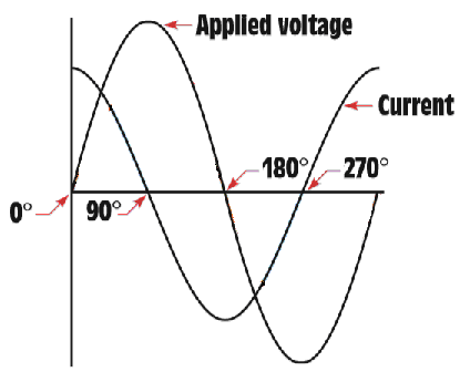
As can be seen from the above figure,
At 0°, value for the applied voltage is zero, while the graph for current is at its positive peak.
At 90°, value for the applied voltage is at its positive peak , while the graph for current is at zero.
At 180°, value for the applied voltage is zero, while the graph for current reaches negative peak.
At 270°, value for the applied voltage reaches negative peak, while the graph for current rises towards zero from the negative peak.
From the above pattern it can be interpreted that current leads the applied voltage by in pure capacitive circuit.
Want to see more full solutions like this?
Chapter 22 Solutions
Mindtap Electrical, 4 Terms (24 Months) Printed Access Card For Herman's Delmar's Standard Textbook Of Electricity, 6th (mindtap Course List)


- Answer A is wrong.arrow_forwardThe part of machine level instruction, which tells the central processor what was to be done is: A. Address B. None of the above C. Operation code D. Operandarrow_forwardWhich of the following statement is TRUE? 1. In RISC processors, each instruction requires only two clock cycles to complete, resulting in consistent execution time 2. RISC has more transistors and fewer registers 3. RISC has more registers and fewer transistorsarrow_forward
- A half-wave controlled rectifier is supplied by a 230 Vrms voltage source and has load resistance of 2502. Calculate the delay angle a that produces a load-absorbed power of 200W.arrow_forwardnot use ai pleasearrow_forwardFigure 1 shows a half-wave controlled rectifier which is supplied by a Vin = 120 Vrms voltage source. Assume that the load resistance is R = 10 2. Determine: a) The firing angle a of the thyristor to produce an average output voltage 50Vdc. Vin=Vmsinoot b) The average power Po absorbed by the load R. Figure 1 R = 1092arrow_forward
- Q1. What is power dissipation in the Zener diode circuit given for a) RL=100 Ohm ? b) RL=∞arrow_forwardThe one-line diagram of an unloaded power system is shown below. Reactances of the two sections of transmission line are shown on the diagram. The generators and transformers are rated as follows: 20 MVA, 13.8 kV, X = 0.20 p.u Generator 1: Generator 2: Generator 3: 30 MVA, 18 kV, X = 0.20 p.u Transformer Ti: Transformer T2: 30 MVA, 20 kV, X = 0.20 p.u 25 MVA, 220Y/13.8A kV, X = 10% Three single-phase units each rated 10 MVA, 127/18 kV, X = 10% HT sides connected in wye Transformer T3: LT sides connected in delta 35 MVA, 220Y/22Y KV, X = 10% j80 Q j100 Q Line 1 Line 2 T₁ T₂ Draw the impedance diagram with all reactances marked in per unit. Choose a base of 50 MVA, 13.8 kV in the circuit of generator 1.arrow_forwardntotnarrow_forward
 Delmar's Standard Textbook Of ElectricityElectrical EngineeringISBN:9781337900348Author:Stephen L. HermanPublisher:Cengage Learning