
Concept explainers
Videos
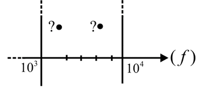
- Determine the frequencies (in kHz) at the points indicated on the plot in Fig. 22.104(a).
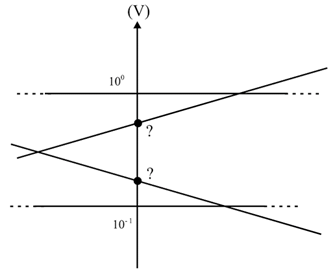
- Determine the voltages (in mV) at the points indicated on the plot in Fig. 22.104(b).
(a)
The frequencies at the points indicated in the plot
Answer to Problem 1P
The frequencies at the points are
Explanation of Solution
Given:
Formula used:
The frequency at the point is calculated by
Calculation:
The distance of the first point,
The distance between two vertical axes is
The value of the first point,
The value of the first point is
The values of the second point is,
The value of the second point is
Conclusion:
Thus, the value of the first point is
(b)
The voltages at the points indicated on the plot
Answer to Problem 1P
The voltage of the top point is 527.5mVand the bottom point is 181.7mV
Explanation of Solution
Given:
Formula used:
The voltage at the point is calculated by
Calculation:
The total length of the vertical axis is,
Using a scale on the vertical axis, from the plot, we can find that the top and bottom points are at a fractionof total length of the vertical axis from the bottom.
The voltage value of the top point is
The voltage of the top point is 527.5mV
The voltage value of the bottom point is
The voltage of the bottom point is 181.7mV
Conclusion:
Thus, the voltage of the top point is 527.5mVand the voltage of the bottom point is 181.7mV
Want to see more full solutions like this?
Chapter 22 Solutions
Introductory Circuit Analysis (13th Edition)
Additional Engineering Textbook Solutions
Java: An Introduction to Problem Solving and Programming (8th Edition)
Modern Database Management
Thermodynamics: An Engineering Approach
Electric Circuits. (11th Edition)
Database Concepts (8th Edition)


- "Please, the answer must be documented from a book, experience, or accurate information without using artificial intelligence." Write an Arduino program to read the status of two push buttons connected to pins 2&3 respectively and flash ON two LED's connected to pins 12&13 respectively according to the following scenario: If pin 2 is HIGH let LED 12 flash with delay of 400ms, and if pin 3 HIGH, let LED 13 flash ON with delay of 300ms.arrow_forward"Based on a source, book, or expertise in the specialized field, I need a solution to the question." Write an Arduino program code that controls the intensity of each LED (Ascending and descending) connected to pins {3, 5, 6, 9, 10, 11} successively at an array method) an interval one of one second. (Hint usearrow_forward"Based on a source, book, or expertise in the specialized field, I need a solution to the question." Write an Arduino program to control water tank levels, The 1st Tank level is monitored by ultrasonic sensor No.1, connected to pin Ao on the Arduino board and it's linked to a valve via port 7 to regulate the valve's opening and closing. Similarly, 2nd tank is monitored by ultrasonic sensor No.2, connected to pin A1, and linked to a valve through port 8. Follow the rules in the Table below to control valve and motor activation via port 13 with a 500 ms delay: TRIYAH UN Water level Tank Tank 1<500 (Threshold) Tank 2<300 Tank 1==500 Tank 2<300 Tank 1<500 Tank 2==300 Tank 1=500 Tank 2=300 Motor ON ON SON OFF Valve 1 ON OFF ON OFF Valve 2 ON ON OFF OFFarrow_forward
- "Based on a source, book, or expertise in the specialized field, I need a solution to the question." 1985 Write an Arduino program to flash flash three LED's connected to pins (7, 9 & 11) respectively as shown in figure below: (Note: T₁-T3-5s & T₂=3s) LED₁ (pin 7) LED2 (pin 9) LED3 (pin 11) T₁ T2 T3 1406arrow_forward"Based on a source, book, or expertise in the specialized field, I need a solution to the question." Write an Arduino programming code that activates eight LEDs connected to pins 0 to 7 successively with an interval of 1 second when switch S₁ connected to pins 8 is turned ON, and all LEDs are activated when switch S₂ connected to pins 9 is turned off. (Hint: use array method).arrow_forwardDetermine X(w) for the given function shown in Figure (1) by applying the differentiation property of the Fourier Transform. 1 x(t) Figure (1) -1 1 2arrow_forward
- 5. Determine an expression for vo as a function of vs in the circuit shown below. Assume the operational amplifier is ideal (10 pts) 162 + + 212 10052} -j 100-52 Noarrow_forward4. A 120 volt rms voltage source supplies 20 Amps rms to a load. The load requires 2,078 watts. What is the reactive power (Vars) and the power factor of the load. Assume the load is inductive. (15pts)arrow_forward6. Determine the rms value of the voltage cyclical waveform shown below. (15 pts) Zv N 시 ما Msec 8arrow_forward
 Power System Analysis and Design (MindTap Course ...Electrical EngineeringISBN:9781305632134Author:J. Duncan Glover, Thomas Overbye, Mulukutla S. SarmaPublisher:Cengage Learning