
EBK MECHANICS OF MATERIALS
7th Edition
ISBN: 9780100257061
Author: BEER
Publisher: YUZU
expand_more
expand_more
format_list_bulleted
Videos
Textbook Question
Chapter 2.13, Problem 97P
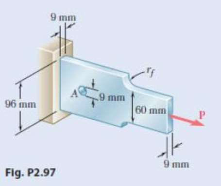
2.97 Knowing that the hole has a diameter of 9 mm, determine (a) the radius rf of the fillets for which the same maximum stress occurs at the hole A and at the fillets, (b) the corresponding maximum allowable load P if the allowable stress is 100 MPa.
Expert Solution & Answer
Want to see the full answer?
Check out a sample textbook solution
Students have asked these similar questions
mylabmastering.pearson.com
Chapter 12 - Lecture Notes.pptx: (MAE 272-01) (SP25) DY...
P Pearson MyLab and Mastering
Scores
Air modeled as an ideal gas enters an insulated compressor at a temperature of 300 K and 100 kPa, and leaves at 600 kPa. The mass flowrate of air entering the compressor is 50 kg/hr, and the power consumed by the compressor is 3 kW. (Rair = 0.287 kJ/kg-K, k = 1.4, cp = 1.0045 kJ/kg-K, cv = 0.718 kJ/kg-K)
Determine the isentropic exit temperature (Te,s) of the air in [K].
Determine the actual exit temperature (Te) of the air in [K].
Determine the isentropic efficiency of the compressor. (Answer: ηc,s = 93.3%)
Determine the rate of entropy generated through the compressor in [kW/K]. (Answer: Ṡgen = 0.000397 kW/K)
mylabmastering.pearson.com
Chapter 12 - Lecture Notes.pptx: (MAE 272-01) (SP25) DY...
P Pearson MyLab and Mastering
Scores
Chapter 2 Solutions
EBK MECHANICS OF MATERIALS
Ch. 2.1 - A nylon thread is subjected to a 8.5-N tension...Ch. 2.1 - A 4.8-ft-long steel wire of 14 -in.-diameter is...Ch. 2.1 - An 18-m-long steel wire of 5-mm diameter is to be...Ch. 2.1 - Two gage marks are placed exactly 250 mm apart on...Ch. 2.1 - An aluminum pipe must not stretch more than 0.05...Ch. 2.1 - A control rod made of yellow brass must not...Ch. 2.1 - A steel control rod is 5.5 ft long and must not...Ch. 2.1 - A cast-iron tube is used to support a compressive...Ch. 2.1 - A 4-m-long steel rod must not stretch more than 3...Ch. 2.1 - A nylon thread is to be subjected to a 10-N...
Ch. 2.1 - A block of 10-in. length and 1.8 1.6-in. cross...Ch. 2.1 - A square yellow-brass bar must not stretch more...Ch. 2.1 - Rod BD is made of steel (E = 29 106 psi) and is...Ch. 2.1 - The 4-mm-diameter cable BC is made of a steel with...Ch. 2.1 - A single axial load of magnitude P = 15 kips is...Ch. 2.1 - A 250-mm-long aluminum tube (E = 70 GPa) of 36-mm...Ch. 2.1 - The specimen shown has been cut from a...Ch. 2.1 - The brass tube AB (E = 105 GPa) has a...Ch. 2.1 - Both portions of the rod ABC are made of an...Ch. 2.1 - The rod ABC is made of an aluminum for which E =...Ch. 2.1 - For the steel truss (E = 200 GPa) and loading...Ch. 2.1 - For the steel truss (E = 29 106 psi) and loading...Ch. 2.1 - Members AB and BC are made of steel (E = 29 106...Ch. 2.1 - The steel frame (E = 200 GPa) shown has a diagonal...Ch. 2.1 - Link BD is made of brass (E = 105 GPa) and has a...Ch. 2.1 - Members ABC and DEF are joined with steel links (E...Ch. 2.1 - Each of the links AB and CD is made of aluminum (E...Ch. 2.1 - The length of the 332-in.-diameter steel wire CD...Ch. 2.1 - A homogenous cable of length L and uniform cross...Ch. 2.1 - The vertical load P is applied at the center A of...Ch. 2.1 - Denoting by the "engineering strain'' in a...Ch. 2.1 - The volume of a tensile specimen is essentially...Ch. 2.3 - An axial centric force of magnitude P = 450 kN is...Ch. 2.3 - An axial centric force of magnitude P = 450 kN is...Ch. 2.3 - The 4.5-ft concrete post is reinforced with six...Ch. 2.3 - The 4.5-ft concrete post is reinforced with six...Ch. 2.3 - An axial force of 200 kW is applied to the...Ch. 2.3 - The length of the assembly shown decreases by 0.40...Ch. 2.3 - A polystyrene rod consisting of two cylindrical...Ch. 2.3 - Three steel rods (E = 29 106 psi) support an...Ch. 2.3 - Fig. P2.41 2.41 Two cylindrical rods, one of steel...Ch. 2.3 - Solve Prob. 2.41, assuming that rod AC is made of...Ch. 2.3 - Each of the rods BD and CE is made of brass (E =...Ch. 2.3 - The rigid bar AD is supported by two steel wires...Ch. 2.3 - The rigid bar ABC is suspended from three wines of...Ch. 2.3 - The rigid bar AD is supported by two steel wires...Ch. 2.3 - The aluminum shell is fully bonded to the brass...Ch. 2.3 - The aluminum shell is fully bonded to the brass...Ch. 2.3 - The brass shell (b = 11.6 10-6/F) is fully bonded...Ch. 2.3 - The concrete post (Ec = 3.6 106) psi and c = 5.5 ...Ch. 2.3 - A rod consisting of two cylindrical portions AB...Ch. 2.3 - A rod consisting of two cylindrical portions AB...Ch. 2.3 - Fig. P2.52 2.52 A rod consisting of two...Ch. 2.3 - The steel rails of a railroad (rack (Es = 200GPa,...Ch. 2.3 - Two steel bars (Es = 200 GPa and s = 11.7 10-6/C)...Ch. 2.3 - Determine the maximum load P that can be applied...Ch. 2.3 - An aluminum rod (Ea = 70 GPa, a = 23.6 10-6/C)...Ch. 2.3 - Knowing that a 0.02-in. gap exists when the...Ch. 2.3 - Determine (a) the compressive force in the bars...Ch. 2.3 - At room temperature (20C) a 0.5-mm gap exists...Ch. 2.9 - A standard tension test is used to determine the...Ch. 2.9 - A 2-m length of an aluminum pipe of 240-nun outer...Ch. 2.9 - A line of slope 4:10 has been scribed on a...Ch. 2.9 - A 2.75-kN tensile load is applied to a test coupon...Ch. 2.9 - Fig. P2.65 2.65 In a standard tensile test a steel...Ch. 2.9 - The change in diameter of a large steel bolt is...Ch. 2.9 - The brass rod AD is fitted with a jacket that is...Ch. 2.9 - A fabric used in air-inflated structures is...Ch. 2.9 - A 1-in. square was scribed on the side of a large...Ch. 2.9 - The block shown is made of a magnesium alloy for...Ch. 2.9 - The homogeneous plate ABCD is subjected to a...Ch. 2.9 - For a member under axial loading, express the...Ch. 2.9 - In many situations it is known that the normal...Ch. 2.9 - In many situations physical constraints prevent...Ch. 2.9 - The plastic block shown is bonded to a rigid...Ch. 2.9 - The plastic block shown is bonded to a rigid...Ch. 2.9 - Two blocks of rubber with a modulus of rigidity G...Ch. 2.9 - Fig. P2.77 and P2.78 2.78 Two blocks of rubber...Ch. 2.9 - An elastomeric bearing (G = 130 psi) is used to...Ch. 2.9 - 2.80 For the elastomeric bearing In Prob. 2.79...Ch. 2.9 - A vibration isolation unit consists of two blocks...Ch. 2.9 - Prob. 82PCh. 2.9 - Prob. 83PCh. 2.9 - Prob. 84PCh. 2.9 - Prob. 85PCh. 2.9 - A 2.75-kN tensile load is applied to a test coupon...Ch. 2.9 - A vibration isolation support consists of a rod A...Ch. 2.9 - Prob. 88PCh. 2.9 - Prob. 89PCh. 2.9 - Show that for any given material, the ratio G/E of...Ch. 2.9 - Prob. 91PCh. 2.9 - Prob. 92PCh. 2.13 - Knowing that, for the plate shown, the allowable...Ch. 2.13 - Knowing that P = 38 kN, determine the maximum...Ch. 2.13 - A hole is to be drilled in the plate at A. The...Ch. 2.13 - Fig. P2.95 and P2.96 2.96 (a) For P = 13 kips and...Ch. 2.13 - 2.97 Knowing that the hole has a diameter of 9 mm,...Ch. 2.13 - For P = 100 kN, determine the minimum plate...Ch. 2.13 - Prob. 99PCh. 2.13 - A centric axial force is applied to the steel bar...Ch. 2.13 - The cylindrical rod AB has a length L = 5 ft and a...Ch. 2.13 - Fig. P2.101 and P.102 2.102 The cylindrical rod AB...Ch. 2.13 - Rod AB is made of a mild steel that is assumed to...Ch. 2.13 - Prob. 104PCh. 2.13 - Rod ABC consists of two cylindrical portions and...Ch. 2.13 - Prob. 106PCh. 2.13 - Prob. 107PCh. 2.13 - Prob. 108PCh. 2.13 - Each cable has a cross-sectional area of 100 mm2...Ch. 2.13 - Prob. 110PCh. 2.13 - Two tempered-steel bars, each 316 in. thick, are...Ch. 2.13 - Prob. 112PCh. 2.13 - Prob. 113PCh. 2.13 - Prob. 114PCh. 2.13 - Prob. 115PCh. 2.13 - Prob. 116PCh. 2.13 - Prob. 117PCh. 2.13 - Prob. 118PCh. 2.13 - Prob. 119PCh. 2.13 - For the composite bar in Prob. 2.111, determine...Ch. 2.13 - Prob. 121PCh. 2.13 - Bar AB has a cross-sectional area of 1200 mm2 and...Ch. 2.13 - Bar AB has a cross-sectional area of 1200 mm2 and...Ch. 2 - The uniform wire ABC, of unstretched length 2l, is...Ch. 2 - The aluminum rod ABC (E = 10.1 106 psi), which...Ch. 2 - Two solid cylindrical rods are joined at B and...Ch. 2 - Prob. 127RPCh. 2 - Prob. 128RPCh. 2 - Prob. 129RPCh. 2 - A 4-ft concrete post is reinforced with four steel...Ch. 2 - The steel rods BE and CD each have a 16-mm...Ch. 2 - Prob. 132RPCh. 2 - Prob. 133RPCh. 2 - The aluminum test specimen shown is subjected to...Ch. 2 - Prob. 135RP
Knowledge Booster


Learn more about
Need a deep-dive on the concept behind this application? Look no further. Learn more about this topic, mechanical-engineering and related others by exploring similar questions and additional content below.Similar questions
- A metal plate of thickness 200 mm with thermal diffusivity 5.6 x10⁻⁶ m²/s and thermal conductivity 20 W/mK is initially at a uniform temperature of 325°C. Suddenly, the 2 sides of the plate are exposed to a coolant at 15°C for which the convection heat transfer coefficient is 100 W/m²K. Determine temperatures at the surface of the plate after 3 min using (a) Lumped system analysis (b) Analytical one term approximation (c) One dimensional Semi infinite solid Analyze and discuss the resultsarrow_forwardProblem 3 This problem maps back to learning objectives 1-4 & 8. Consider the particle attached to a spring shown below. The particle has a mass m and the spring has a spring constant k. The mass-spring system makes an angle of 0 with respect to the vertical and the distance between point 0 and the particle can be defined as r. The spring is unstretched when r = l. Ꮎ g m a) How many degrees of freedom is this system and what are they? b) Derive the equation(s) of motion that govern the movement of this system.arrow_forwardChapter 12 - Lecture Notes.pptx: (MAE 272-01) (SP25) DY... Scores ■Review Determine the maximum constant speed at which the pilot can travel, so that he experiences a maximum acceleration an = 8g = 78.5 m/s². Express your answer to three significant figures and include the appropriate units. μΑ v = Value Units Submit Request Answer Part B ? Determine the normal force he exerts on the seat of the airplane when the plane is traveling at this speed and is at its lowest point. Express your answer to three significant figures and include the appropriate units. о HÅ N = Value Submit Request Answer Provide Feedback ? Units Next >arrow_forward
- I want to know the Milankovich orbital element constraint equation. Is it e*cos(i) = cos(argp), where e is eccentricity, i is inclination, and argp is arguement of periapsisarrow_forwardThe following data were taken during a one-hour trial run on a single cylinder, single acting, four-stroke diesel engine of cylinder diameter of 175 mm and stroke 225 mm , the speed being constant at 1000 rpm : Indicated mep: 5.5 barsDiam. of rope brake: 1066 mmLoad on brake: 400 NReading of balance: 27 NFuel consumed: 5.7 kgCalorific value: 44.2 MJ/kg Calculate the indicated power, brake power, specific fuel consumption per indicated kWh and per brake kWh , mechanical efficiency, indicated thermal and brake thermal efficiency.arrow_forwardmylabmastering.pearson.com Chapter 12 - Lecture Notes.pptx: (MAE 272-01) (SP25) DY... Document Sharing P Pearson MyLab and Mastering User Settings Part A P Course Home b Success Confirmation of Question Submission | bartleby A particle moves along an Archimedean spiral r = (80) ft, where 0 is given in radians. (Figure 1) If ė = = 4 rad/s and € = 5 rad/s², determine the radial component of the particle's velocity at the instant Express your answer to three significant figures and include the appropriate units. Figure y r = Α ? Vr = Value Units Submit Request Answer Part B Determine the transverse component of the particle's velocity. Express your answer to three significant figures and include the appropriate units. о MÅ ve = Value Submit Request Answer Part C Units ? 1 of 1 Determine the radial component of the particle's acceleration. Express your answer to three significant figures and include the appropriate units. Ar = (80) ft о ΜΑ Value Units ? = π/2 rad.arrow_forward
- Can you help me with a matlab code? I am trying to plot the keplerian orbital elements over time. I would usually find the orbit using cartesian system and then transform into keplerian orbital elements. Is there a way to directly integrate keplerian orbital elements?arrow_forwardmylabmastering.pearson.com Chapter 12 - Lecture Notes.pptx: (MAE 272-01) (SP25) DY... P Pearson MyLab and Mastering Scoresarrow_forwardK mylabmastering.pearson.com Chapter 12 - Lecture Notes.pptx: (MAE 272-01) (SP25) DY... P Pearson MyLab and Mastering Mastering Engineering Back to my courses Course Home Scores Course Homearrow_forwardK mylabmastering.pearson.com Chapter 12 - Lecture Notes.pptx: (MAE 272-01) (SP25) DY... P Pearson MyLab and Mastering Mastering Engineering Back to my courses Course Home Scores Course Homearrow_forwardChapter 12 - Lecture Notes.pptx: (MAE 272-01) (SP25) DY... Scoresarrow_forwardIn a single cylinder, four stroke, single acting gas engine, the cylinder diameter is 180 mm and the stroke is 350 mm . When running at 250 rpm , the mean area of the indicator diagram taken off the engine is 355 mm² , length of diagram 75 mm , scale of the indicator spring 90 kN/m sq per mm , and the number of explosions was counted to be 114 per minute. Calculate the indicated power. so i have already asked this question and got a good answer, however on step 4, i dont understand how they reached 18.43 KW. When i do the math provided, i get the answer 7195.566. Where am i going wrong? thanks StepsTo clarify how we determined the Indicated Power, I'll go over each step in detail. Step 1: Comprehending the Provided Information - Cylinder diameter (in meters) = 180 mm = 0.18 m - Stroke length (in meters) = 350 mm = 0.35 m - Engine speed = 250 rpm -Indicator diagram mean area = 355 mm² The diagram's length is 75 mm; its spring scale is 90 kN/m² per mm, or 90,000 N/m² per mm; and…arrow_forwardarrow_back_iosSEE MORE QUESTIONSarrow_forward_ios
Recommended textbooks for you
 Elements Of ElectromagneticsMechanical EngineeringISBN:9780190698614Author:Sadiku, Matthew N. O.Publisher:Oxford University Press
 Mechanics of Materials (10th Edition)Mechanical EngineeringISBN:9780134319650Author:Russell C. HibbelerPublisher:PEARSON
 Thermodynamics: An Engineering ApproachMechanical EngineeringISBN:9781259822674Author:Yunus A. Cengel Dr., Michael A. BolesPublisher:McGraw-Hill Education
 Control Systems EngineeringMechanical EngineeringISBN:9781118170519Author:Norman S. NisePublisher:WILEY
 Mechanics of Materials (MindTap Course List)Mechanical EngineeringISBN:9781337093347Author:Barry J. Goodno, James M. GerePublisher:Cengage Learning
 Engineering Mechanics: StaticsMechanical EngineeringISBN:9781118807330Author:James L. Meriam, L. G. Kraige, J. N. BoltonPublisher:WILEY
Elements Of Electromagnetics
Mechanical Engineering
ISBN:9780190698614
Author:Sadiku, Matthew N. O.
Publisher:Oxford University Press
Mechanics of Materials (10th Edition)
Mechanical Engineering
ISBN:9780134319650
Author:Russell C. Hibbeler
Publisher:PEARSON
Thermodynamics: An Engineering Approach
Mechanical Engineering
ISBN:9781259822674
Author:Yunus A. Cengel Dr., Michael A. Boles
Publisher:McGraw-Hill Education
Control Systems Engineering
Mechanical Engineering
ISBN:9781118170519
Author:Norman S. Nise
Publisher:WILEY
Mechanics of Materials (MindTap Course List)
Mechanical Engineering
ISBN:9781337093347
Author:Barry J. Goodno, James M. Gere
Publisher:Cengage Learning
Engineering Mechanics: Statics
Mechanical Engineering
ISBN:9781118807330
Author:James L. Meriam, L. G. Kraige, J. N. Bolton
Publisher:WILEY
Differences between Temporary Joining and Permanent Joining.; Author: Academic Gain Tutorials;https://www.youtube.com/watch?v=PTr8QZhgXyg;License: Standard Youtube License