
Mechanics of Materials, 7th Edition
7th Edition
ISBN: 9780073398235
Author: Ferdinand P. Beer, E. Russell Johnston Jr., John T. DeWolf, David F. Mazurek
Publisher: McGraw-Hill Education
expand_more
expand_more
format_list_bulleted
Concept explainers
Videos
Textbook Question
Chapter 2.1, Problem 27P
Each of the links AB and CD is made of aluminum (E = 10.9 × 10⁶ psi) and has a cross-sectional area of 0.2 in2. Knowing that they support the rigid member BC, determine the deflection of point E.
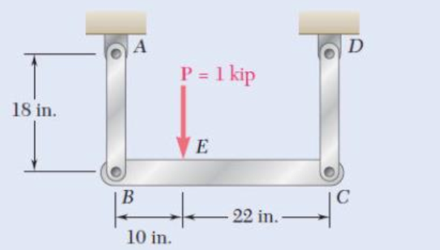
Fig. P2.27
Expert Solution & Answer
Want to see the full answer?
Check out a sample textbook solution
Students have asked these similar questions
CORRECT AND DETAILED SOLUTION WITH FBD ONLY. I WILL UPVOTE THANK YOU. CORRECT ANSWER IS ALREADY PROVIDED. I NEED FBD
A short plate is attached to the center of the shaft as shown. The bottom of the shaft is fixed to the ground.Given: a = 75 mm, h = 125 mm, D = 38 mmP1 = 24 kN, P2 = 28 kN1. Calculate the maximum torsional stress in the shaft, in MPa.2. Calculate the maximum flexural stress in the shaft, in MPa.3. Calculate the maximum horizontal shear stress in the shaft, in MPa.ANSWERS: (1) 167.07 MPa; (2) 679.77 MPa; (3) 28.22 MPa
CORRECT AND DETAILED SOLUTION WITH FBD ONLY. I WILL UPVOTE THANK YOU. CORRECT ANSWER IS ALREADY PROVIDED. I REALLY NEED FBD.
The roof truss shown carries roof loads, where P = 10 kN. The truss is consisting of circular arcs top andbottom chords with radii R + h and R, respectively.Given: h = 1.2 m, R = 10 m, s = 2 m.Allowable member stresses:Tension = 250 MPaCompression = 180 MPa1. If member KL has square section, determine the minimum dimension (mm).2. If member KL has circular section, determine the minimum diameter (mm).3. If member GH has circular section, determine the minimum diameter (mm).ANSWERS: (1) 31.73 mm; (2) 35.81 mm; (3) 18.49 mm
PROBLEM 3.23
3.23 Under normal operating condi-
tions a motor exerts a torque of
magnitude TF at F. The shafts
are made of a steel for which
the allowable shearing stress is
82 MPa and have diameters of
dCDE=24 mm and dFGH = 20
mm. Knowing that rp = 165
mm and rg114 mm, deter-
mine the largest torque TF
which may be exerted at F.
TF
F
rG-
rp
B
CH
TE
E
Chapter 2 Solutions
Mechanics of Materials, 7th Edition
Ch. 2.1 - A nylon thread is subjected to a 8.5-N tension...Ch. 2.1 - A 4.8-ft-long steel wire of 14 -in.-diameter is...Ch. 2.1 - An 18-m-long steel wire of 5-mm diameter is to be...Ch. 2.1 - Two gage marks are placed exactly 250 mm apart on...Ch. 2.1 - An aluminum pipe must not stretch more than 0.05...Ch. 2.1 - A control rod made of yellow brass must not...Ch. 2.1 - A steel control rod is 5.5 ft long and must not...Ch. 2.1 - A cast-iron tube is used to support a compressive...Ch. 2.1 - A 4-m-long steel rod must not stretch more than 3...Ch. 2.1 - A nylon thread is to be subjected to a 10-N...
Ch. 2.1 - A block of 10-in. length and 1.8 1.6-in. cross...Ch. 2.1 - A square yellow-brass bar must not stretch more...Ch. 2.1 - Rod BD is made of steel (E = 29 106 psi) and is...Ch. 2.1 - The 4-mm-diameter cable BC is made of a steel with...Ch. 2.1 - A single axial load of magnitude P = 15 kips is...Ch. 2.1 - A 250-mm-long aluminum tube (E = 70 GPa) of 36-mm...Ch. 2.1 - The specimen shown has been cut from a...Ch. 2.1 - The brass tube AB (E = 105 GPa) has a...Ch. 2.1 - Both portions of the rod ABC are made of an...Ch. 2.1 - The rod ABC is made of an aluminum for which E =...Ch. 2.1 - For the steel truss (E = 200 GPa) and loading...Ch. 2.1 - For the steel truss (E = 29 106 psi) and loading...Ch. 2.1 - Members AB and BC are made of steel (E = 29 106...Ch. 2.1 - The steel frame (E = 200 GPa) shown has a diagonal...Ch. 2.1 - Link BD is made of brass (E = 105 GPa) and has a...Ch. 2.1 - Members ABC and DEF are joined with steel links (E...Ch. 2.1 - Each of the links AB and CD is made of aluminum (E...Ch. 2.1 - The length of the 332-in.-diameter steel wire CD...Ch. 2.1 - A homogenous cable of length L and uniform cross...Ch. 2.1 - The vertical load P is applied at the center A of...Ch. 2.1 - Denoting by the "engineering strain'' in a...Ch. 2.1 - The volume of a tensile specimen is essentially...Ch. 2.3 - An axial centric force of magnitude P = 450 kN is...Ch. 2.3 - An axial centric force of magnitude P = 450 kN is...Ch. 2.3 - The 4.5-ft concrete post is reinforced with six...Ch. 2.3 - The 4.5-ft concrete post is reinforced with six...Ch. 2.3 - An axial force of 200 kW is applied to the...Ch. 2.3 - The length of the assembly shown decreases by 0.40...Ch. 2.3 - A polystyrene rod consisting of two cylindrical...Ch. 2.3 - Three steel rods (E = 29 106 psi) support an...Ch. 2.3 - Fig. P2.41 2.41 Two cylindrical rods, one of steel...Ch. 2.3 - Solve Prob. 2.41, assuming that rod AC is made of...Ch. 2.3 - Each of the rods BD and CE is made of brass (E =...Ch. 2.3 - The rigid bar AD is supported by two steel wires...Ch. 2.3 - The rigid bar ABC is suspended from three wines of...Ch. 2.3 - The rigid bar AD is supported by two steel wires...Ch. 2.3 - The aluminum shell is fully bonded to the brass...Ch. 2.3 - The aluminum shell is fully bonded to the brass...Ch. 2.3 - The brass shell (b = 11.6 10-6/F) is fully bonded...Ch. 2.3 - The concrete post (Ec = 3.6 106) psi and c = 5.5 ...Ch. 2.3 - A rod consisting of two cylindrical portions AB...Ch. 2.3 - A rod consisting of two cylindrical portions AB...Ch. 2.3 - Fig. P2.52 2.52 A rod consisting of two...Ch. 2.3 - The steel rails of a railroad (rack (Es = 200GPa,...Ch. 2.3 - Two steel bars (Es = 200 GPa and s = 11.7 10-6/C)...Ch. 2.3 - Determine the maximum load P that can be applied...Ch. 2.3 - An aluminum rod (Ea = 70 GPa, a = 23.6 10-6/C)...Ch. 2.3 - Knowing that a 0.02-in. gap exists when the...Ch. 2.3 - Determine (a) the compressive force in the bars...Ch. 2.3 - At room temperature (20C) a 0.5-mm gap exists...Ch. 2.9 - A standard tension test is used to determine the...Ch. 2.9 - A 2-m length of an aluminum pipe of 240-nun outer...Ch. 2.9 - A line of slope 4:10 has been scribed on a...Ch. 2.9 - A 2.75-kN tensile load is applied to a test coupon...Ch. 2.9 - Fig. P2.65 2.65 In a standard tensile test a steel...Ch. 2.9 - The change in diameter of a large steel bolt is...Ch. 2.9 - The brass rod AD is fitted with a jacket that is...Ch. 2.9 - A fabric used in air-inflated structures is...Ch. 2.9 - A 1-in. square was scribed on the side of a large...Ch. 2.9 - The block shown is made of a magnesium alloy for...Ch. 2.9 - The homogeneous plate ABCD is subjected to a...Ch. 2.9 - For a member under axial loading, express the...Ch. 2.9 - In many situations it is known that the normal...Ch. 2.9 - In many situations physical constraints prevent...Ch. 2.9 - The plastic block shown is bonded to a rigid...Ch. 2.9 - The plastic block shown is bonded to a rigid...Ch. 2.9 - Two blocks of rubber with a modulus of rigidity G...Ch. 2.9 - Fig. P2.77 and P2.78 2.78 Two blocks of rubber...Ch. 2.9 - An elastomeric bearing (G = 130 psi) is used to...Ch. 2.9 - 2.80 For the elastomeric bearing In Prob. 2.79...Ch. 2.9 - A vibration isolation unit consists of two blocks...Ch. 2.9 - Prob. 82PCh. 2.9 - Prob. 83PCh. 2.9 - Prob. 84PCh. 2.9 - Prob. 85PCh. 2.9 - A 2.75-kN tensile load is applied to a test coupon...Ch. 2.9 - A vibration isolation support consists of a rod A...Ch. 2.9 - Prob. 88PCh. 2.9 - Prob. 89PCh. 2.9 - Show that for any given material, the ratio G/E of...Ch. 2.9 - Prob. 91PCh. 2.9 - Prob. 92PCh. 2.13 - Knowing that, for the plate shown, the allowable...Ch. 2.13 - Knowing that P = 38 kN, determine the maximum...Ch. 2.13 - A hole is to be drilled in the plate at A. The...Ch. 2.13 - Fig. P2.95 and P2.96 2.96 (a) For P = 13 kips and...Ch. 2.13 - 2.97 Knowing that the hole has a diameter of 9 mm,...Ch. 2.13 - For P = 100 kN, determine the minimum plate...Ch. 2.13 - Prob. 99PCh. 2.13 - A centric axial force is applied to the steel bar...Ch. 2.13 - The cylindrical rod AB has a length L = 5 ft and a...Ch. 2.13 - Fig. P2.101 and P.102 2.102 The cylindrical rod AB...Ch. 2.13 - Rod AB is made of a mild steel that is assumed to...Ch. 2.13 - Prob. 104PCh. 2.13 - Rod ABC consists of two cylindrical portions and...Ch. 2.13 - Prob. 106PCh. 2.13 - Prob. 107PCh. 2.13 - Prob. 108PCh. 2.13 - Each cable has a cross-sectional area of 100 mm2...Ch. 2.13 - Prob. 110PCh. 2.13 - Two tempered-steel bars, each 316 in. thick, are...Ch. 2.13 - Prob. 112PCh. 2.13 - Prob. 113PCh. 2.13 - Prob. 114PCh. 2.13 - Prob. 115PCh. 2.13 - Prob. 116PCh. 2.13 - Prob. 117PCh. 2.13 - Prob. 118PCh. 2.13 - Prob. 119PCh. 2.13 - For the composite bar in Prob. 2.111, determine...Ch. 2.13 - Prob. 121PCh. 2.13 - Bar AB has a cross-sectional area of 1200 mm2 and...Ch. 2.13 - Bar AB has a cross-sectional area of 1200 mm2 and...Ch. 2 - The uniform wire ABC, of unstretched length 2l, is...Ch. 2 - The aluminum rod ABC (E = 10.1 106 psi), which...Ch. 2 - Two solid cylindrical rods are joined at B and...Ch. 2 - Prob. 127RPCh. 2 - Prob. 128RPCh. 2 - Prob. 129RPCh. 2 - A 4-ft concrete post is reinforced with four steel...Ch. 2 - The steel rods BE and CD each have a 16-mm...Ch. 2 - Prob. 132RPCh. 2 - Prob. 133RPCh. 2 - The aluminum test specimen shown is subjected to...Ch. 2 - Prob. 135RP
Knowledge Booster


Learn more about
Need a deep-dive on the concept behind this application? Look no further. Learn more about this topic, mechanical-engineering and related others by exploring similar questions and additional content below.Similar questions
- 1. (16%) (a) If a ductile material fails under pure torsion, please explain the failure mode and describe the observed plane of failure. (b) Suppose a prismatic beam is subjected to equal and opposite couples as shown in Fig. 1. Please sketch the deformation and the stress distribution of the cross section. M M Fig. 1 (c) Describe the definition of the neutral axis. (d) Describe the definition of the modular ratio.arrow_forwardusing the theorem of three moments, find all the moments, I only need concise calculations with minimal explanations. The correct answers are provided at the bottomarrow_forwardMechanics of materialsarrow_forward
- practise questionarrow_forwardCan you provide steps and an explaination on how the height value to calculate the Pressure at point B is (-5-3.5) and the solution is 86.4kPa.arrow_forwardPROBLEM 3.46 The solid cylindrical rod BC of length L = 600 mm is attached to the rigid lever AB of length a = 380 mm and to the support at C. When a 500 N force P is applied at A, design specifications require that the displacement of A not exceed 25 mm when a 500 N force P is applied at A For the material indicated determine the required diameter of the rod. Aluminium: Tall = 65 MPa, G = 27 GPa. Aarrow_forward
- Find the equivalent mass of the rocker arm assembly with respect to the x coordinate. k₁ mi m2 k₁arrow_forward2. Figure below shows a U-tube manometer open at both ends and containing a column of liquid mercury of length l and specific weight y. Considering a small displacement x of the manometer meniscus from its equilibrium position (or datum), determine the equivalent spring constant associated with the restoring force. Datum Area, Aarrow_forward1. The consequences of a head-on collision of two automobiles can be studied by considering the impact of the automobile on a barrier, as shown in figure below. Construct a mathematical model (i.e., draw the diagram) by considering the masses of the automobile body, engine, transmission, and suspension and the elasticity of the bumpers, radiator, sheet metal body, driveline, and engine mounts.arrow_forward
arrow_back_ios
SEE MORE QUESTIONS
arrow_forward_ios
Recommended textbooks for you
 Elements Of ElectromagneticsMechanical EngineeringISBN:9780190698614Author:Sadiku, Matthew N. O.Publisher:Oxford University Press
 Mechanics of Materials (10th Edition)Mechanical EngineeringISBN:9780134319650Author:Russell C. HibbelerPublisher:PEARSON
 Thermodynamics: An Engineering ApproachMechanical EngineeringISBN:9781259822674Author:Yunus A. Cengel Dr., Michael A. BolesPublisher:McGraw-Hill Education
 Control Systems EngineeringMechanical EngineeringISBN:9781118170519Author:Norman S. NisePublisher:WILEY
 Mechanics of Materials (MindTap Course List)Mechanical EngineeringISBN:9781337093347Author:Barry J. Goodno, James M. GerePublisher:Cengage Learning
 Engineering Mechanics: StaticsMechanical EngineeringISBN:9781118807330Author:James L. Meriam, L. G. Kraige, J. N. BoltonPublisher:WILEY
Elements Of Electromagnetics
Mechanical Engineering
ISBN:9780190698614
Author:Sadiku, Matthew N. O.
Publisher:Oxford University Press
Mechanics of Materials (10th Edition)
Mechanical Engineering
ISBN:9780134319650
Author:Russell C. Hibbeler
Publisher:PEARSON
Thermodynamics: An Engineering Approach
Mechanical Engineering
ISBN:9781259822674
Author:Yunus A. Cengel Dr., Michael A. Boles
Publisher:McGraw-Hill Education
Control Systems Engineering
Mechanical Engineering
ISBN:9781118170519
Author:Norman S. Nise
Publisher:WILEY
Mechanics of Materials (MindTap Course List)
Mechanical Engineering
ISBN:9781337093347
Author:Barry J. Goodno, James M. Gere
Publisher:Cengage Learning
Engineering Mechanics: Statics
Mechanical Engineering
ISBN:9781118807330
Author:James L. Meriam, L. G. Kraige, J. N. Bolton
Publisher:WILEY
Solids: Lesson 53 - Slope and Deflection of Beams Intro; Author: Jeff Hanson;https://www.youtube.com/watch?v=I7lTq68JRmY;License: Standard YouTube License, CC-BY