
Mechanics of Materials, 7th Edition
7th Edition
ISBN: 9780073398235
Author: Ferdinand P. Beer, E. Russell Johnston Jr., John T. DeWolf, David F. Mazurek
Publisher: McGraw-Hill Education
expand_more
expand_more
format_list_bulleted
Concept explainers
Videos
Textbook Question
Chapter 2.1, Problem 17P
The specimen shown has been cut from a
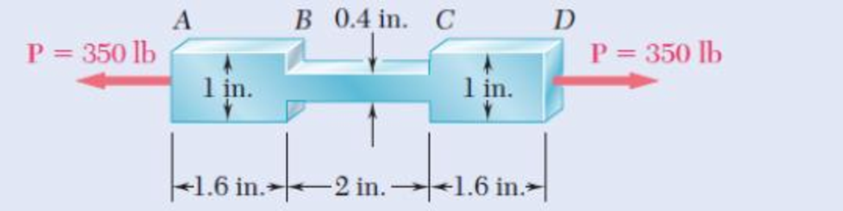
Fig. P2.17
Expert Solution & Answer
Want to see the full answer?
Check out a sample textbook solution
Students have asked these similar questions
Find the equivalent mass of the rocker arm assembly with respect to the x coordinate.
k₁
mi
m2
k₁
2. Figure below shows a U-tube manometer open at both ends and containing a column of liquid
mercury of length l and specific weight y. Considering a small displacement x of the manometer
meniscus from its equilibrium position (or datum), determine the equivalent spring constant associated
with the restoring force.
Datum
Area, A
1. The consequences of a head-on collision of two automobiles can be studied by considering the
impact of the automobile on a barrier, as shown in figure below. Construct a mathematical model (i.e.,
draw the diagram) by considering the masses of the automobile body, engine, transmission, and
suspension and the elasticity of the bumpers, radiator, sheet metal body, driveline, and engine
mounts.
Chapter 2 Solutions
Mechanics of Materials, 7th Edition
Ch. 2.1 - A nylon thread is subjected to a 8.5-N tension...Ch. 2.1 - A 4.8-ft-long steel wire of 14 -in.-diameter is...Ch. 2.1 - An 18-m-long steel wire of 5-mm diameter is to be...Ch. 2.1 - Two gage marks are placed exactly 250 mm apart on...Ch. 2.1 - An aluminum pipe must not stretch more than 0.05...Ch. 2.1 - A control rod made of yellow brass must not...Ch. 2.1 - A steel control rod is 5.5 ft long and must not...Ch. 2.1 - A cast-iron tube is used to support a compressive...Ch. 2.1 - A 4-m-long steel rod must not stretch more than 3...Ch. 2.1 - A nylon thread is to be subjected to a 10-N...
Ch. 2.1 - A block of 10-in. length and 1.8 1.6-in. cross...Ch. 2.1 - A square yellow-brass bar must not stretch more...Ch. 2.1 - Rod BD is made of steel (E = 29 106 psi) and is...Ch. 2.1 - The 4-mm-diameter cable BC is made of a steel with...Ch. 2.1 - A single axial load of magnitude P = 15 kips is...Ch. 2.1 - A 250-mm-long aluminum tube (E = 70 GPa) of 36-mm...Ch. 2.1 - The specimen shown has been cut from a...Ch. 2.1 - The brass tube AB (E = 105 GPa) has a...Ch. 2.1 - Both portions of the rod ABC are made of an...Ch. 2.1 - The rod ABC is made of an aluminum for which E =...Ch. 2.1 - For the steel truss (E = 200 GPa) and loading...Ch. 2.1 - For the steel truss (E = 29 106 psi) and loading...Ch. 2.1 - Members AB and BC are made of steel (E = 29 106...Ch. 2.1 - The steel frame (E = 200 GPa) shown has a diagonal...Ch. 2.1 - Link BD is made of brass (E = 105 GPa) and has a...Ch. 2.1 - Members ABC and DEF are joined with steel links (E...Ch. 2.1 - Each of the links AB and CD is made of aluminum (E...Ch. 2.1 - The length of the 332-in.-diameter steel wire CD...Ch. 2.1 - A homogenous cable of length L and uniform cross...Ch. 2.1 - The vertical load P is applied at the center A of...Ch. 2.1 - Denoting by the "engineering strain'' in a...Ch. 2.1 - The volume of a tensile specimen is essentially...Ch. 2.3 - An axial centric force of magnitude P = 450 kN is...Ch. 2.3 - An axial centric force of magnitude P = 450 kN is...Ch. 2.3 - The 4.5-ft concrete post is reinforced with six...Ch. 2.3 - The 4.5-ft concrete post is reinforced with six...Ch. 2.3 - An axial force of 200 kW is applied to the...Ch. 2.3 - The length of the assembly shown decreases by 0.40...Ch. 2.3 - A polystyrene rod consisting of two cylindrical...Ch. 2.3 - Three steel rods (E = 29 106 psi) support an...Ch. 2.3 - Fig. P2.41 2.41 Two cylindrical rods, one of steel...Ch. 2.3 - Solve Prob. 2.41, assuming that rod AC is made of...Ch. 2.3 - Each of the rods BD and CE is made of brass (E =...Ch. 2.3 - The rigid bar AD is supported by two steel wires...Ch. 2.3 - The rigid bar ABC is suspended from three wines of...Ch. 2.3 - The rigid bar AD is supported by two steel wires...Ch. 2.3 - The aluminum shell is fully bonded to the brass...Ch. 2.3 - The aluminum shell is fully bonded to the brass...Ch. 2.3 - The brass shell (b = 11.6 10-6/F) is fully bonded...Ch. 2.3 - The concrete post (Ec = 3.6 106) psi and c = 5.5 ...Ch. 2.3 - A rod consisting of two cylindrical portions AB...Ch. 2.3 - A rod consisting of two cylindrical portions AB...Ch. 2.3 - Fig. P2.52 2.52 A rod consisting of two...Ch. 2.3 - The steel rails of a railroad (rack (Es = 200GPa,...Ch. 2.3 - Two steel bars (Es = 200 GPa and s = 11.7 10-6/C)...Ch. 2.3 - Determine the maximum load P that can be applied...Ch. 2.3 - An aluminum rod (Ea = 70 GPa, a = 23.6 10-6/C)...Ch. 2.3 - Knowing that a 0.02-in. gap exists when the...Ch. 2.3 - Determine (a) the compressive force in the bars...Ch. 2.3 - At room temperature (20C) a 0.5-mm gap exists...Ch. 2.9 - A standard tension test is used to determine the...Ch. 2.9 - A 2-m length of an aluminum pipe of 240-nun outer...Ch. 2.9 - A line of slope 4:10 has been scribed on a...Ch. 2.9 - A 2.75-kN tensile load is applied to a test coupon...Ch. 2.9 - Fig. P2.65 2.65 In a standard tensile test a steel...Ch. 2.9 - The change in diameter of a large steel bolt is...Ch. 2.9 - The brass rod AD is fitted with a jacket that is...Ch. 2.9 - A fabric used in air-inflated structures is...Ch. 2.9 - A 1-in. square was scribed on the side of a large...Ch. 2.9 - The block shown is made of a magnesium alloy for...Ch. 2.9 - The homogeneous plate ABCD is subjected to a...Ch. 2.9 - For a member under axial loading, express the...Ch. 2.9 - In many situations it is known that the normal...Ch. 2.9 - In many situations physical constraints prevent...Ch. 2.9 - The plastic block shown is bonded to a rigid...Ch. 2.9 - The plastic block shown is bonded to a rigid...Ch. 2.9 - Two blocks of rubber with a modulus of rigidity G...Ch. 2.9 - Fig. P2.77 and P2.78 2.78 Two blocks of rubber...Ch. 2.9 - An elastomeric bearing (G = 130 psi) is used to...Ch. 2.9 - 2.80 For the elastomeric bearing In Prob. 2.79...Ch. 2.9 - A vibration isolation unit consists of two blocks...Ch. 2.9 - Prob. 82PCh. 2.9 - Prob. 83PCh. 2.9 - Prob. 84PCh. 2.9 - Prob. 85PCh. 2.9 - A 2.75-kN tensile load is applied to a test coupon...Ch. 2.9 - A vibration isolation support consists of a rod A...Ch. 2.9 - Prob. 88PCh. 2.9 - Prob. 89PCh. 2.9 - Show that for any given material, the ratio G/E of...Ch. 2.9 - Prob. 91PCh. 2.9 - Prob. 92PCh. 2.13 - Knowing that, for the plate shown, the allowable...Ch. 2.13 - Knowing that P = 38 kN, determine the maximum...Ch. 2.13 - A hole is to be drilled in the plate at A. The...Ch. 2.13 - Fig. P2.95 and P2.96 2.96 (a) For P = 13 kips and...Ch. 2.13 - 2.97 Knowing that the hole has a diameter of 9 mm,...Ch. 2.13 - For P = 100 kN, determine the minimum plate...Ch. 2.13 - Prob. 99PCh. 2.13 - A centric axial force is applied to the steel bar...Ch. 2.13 - The cylindrical rod AB has a length L = 5 ft and a...Ch. 2.13 - Fig. P2.101 and P.102 2.102 The cylindrical rod AB...Ch. 2.13 - Rod AB is made of a mild steel that is assumed to...Ch. 2.13 - Prob. 104PCh. 2.13 - Rod ABC consists of two cylindrical portions and...Ch. 2.13 - Prob. 106PCh. 2.13 - Prob. 107PCh. 2.13 - Prob. 108PCh. 2.13 - Each cable has a cross-sectional area of 100 mm2...Ch. 2.13 - Prob. 110PCh. 2.13 - Two tempered-steel bars, each 316 in. thick, are...Ch. 2.13 - Prob. 112PCh. 2.13 - Prob. 113PCh. 2.13 - Prob. 114PCh. 2.13 - Prob. 115PCh. 2.13 - Prob. 116PCh. 2.13 - Prob. 117PCh. 2.13 - Prob. 118PCh. 2.13 - Prob. 119PCh. 2.13 - For the composite bar in Prob. 2.111, determine...Ch. 2.13 - Prob. 121PCh. 2.13 - Bar AB has a cross-sectional area of 1200 mm2 and...Ch. 2.13 - Bar AB has a cross-sectional area of 1200 mm2 and...Ch. 2 - The uniform wire ABC, of unstretched length 2l, is...Ch. 2 - The aluminum rod ABC (E = 10.1 106 psi), which...Ch. 2 - Two solid cylindrical rods are joined at B and...Ch. 2 - Prob. 127RPCh. 2 - Prob. 128RPCh. 2 - Prob. 129RPCh. 2 - A 4-ft concrete post is reinforced with four steel...Ch. 2 - The steel rods BE and CD each have a 16-mm...Ch. 2 - Prob. 132RPCh. 2 - Prob. 133RPCh. 2 - The aluminum test specimen shown is subjected to...Ch. 2 - Prob. 135RP
Knowledge Booster


Learn more about
Need a deep-dive on the concept behind this application? Look no further. Learn more about this topic, mechanical-engineering and related others by exploring similar questions and additional content below.Similar questions
- 3.) 15.40 – Collar B moves up at constant velocity vB = 1.5 m/s. Rod AB has length = 1.2 m. The incline is at angle = 25°. Compute an expression for the angular velocity of rod AB, ė and the velocity of end A of the rod (✓✓) as a function of v₂,1,0,0. Then compute numerical answers for ȧ & y_ with 0 = 50°.arrow_forward2.) 15.12 The assembly shown consists of the straight rod ABC which passes through and is welded to the grectangular plate DEFH. The assembly rotates about the axis AC with a constant angular velocity of 9 rad/s. Knowing that the motion when viewed from C is counterclockwise, determine the velocity and acceleration of corner F.arrow_forward500 Q3: The attachment shown in Fig.3 is made of 1040 HR. The static force is 30 kN. Specify the weldment (give the pattern, electrode number, type of weld, length of weld, and leg size). Fig. 3 All dimension in mm 30 kN 100 (10 Marks)arrow_forward
- (read image) (answer given)arrow_forwardA cylinder and a disk are used as pulleys, as shown in the figure. Using the data given in the figure, if a body of mass m = 3 kg is released from rest after falling a height h 1.5 m, find: a) The velocity of the body. b) The angular velocity of the disk. c) The number of revolutions the cylinder has made. T₁ F Rd = 0.2 m md = 2 kg T T₂1 Rc = 0.4 m mc = 5 kg ☐ m = 3 kgarrow_forward(read image) (answer given)arrow_forward
- 11-5. Compute all the dimensional changes for the steel bar when subjected to the loads shown. The proportional limit of the steel is 230 MPa. 265 kN 100 mm 600 kN 25 mm thickness X Z 600 kN 450 mm E=207×103 MPa; μ= 0.25 265 kNarrow_forwardT₁ F Rd = 0.2 m md = 2 kg T₂ Tz1 Rc = 0.4 m mc = 5 kg m = 3 kgarrow_forward2. Find a basis of solutions by the Frobenius method. Try to identify the series as expansions of known functions. (x + 2)²y" + (x + 2)y' - y = 0 ; Hint: Let: z = x+2arrow_forward
- 1. Find a power series solution in powers of x. y" - y' + x²y = 0arrow_forward3. Find a basis of solutions by the Frobenius method. Try to identify the series as expansions of known functions. 8x2y" +10xy' + (x 1)y = 0 -arrow_forwardHello I was going over the solution for this probem and I'm a bit confused on the last part. Can you please explain to me 1^4 was used for the Co of the tubular cross section? Thank you!arrow_forward
arrow_back_ios
SEE MORE QUESTIONS
arrow_forward_ios
Recommended textbooks for you
 Elements Of ElectromagneticsMechanical EngineeringISBN:9780190698614Author:Sadiku, Matthew N. O.Publisher:Oxford University Press
 Mechanics of Materials (10th Edition)Mechanical EngineeringISBN:9780134319650Author:Russell C. HibbelerPublisher:PEARSON
 Thermodynamics: An Engineering ApproachMechanical EngineeringISBN:9781259822674Author:Yunus A. Cengel Dr., Michael A. BolesPublisher:McGraw-Hill Education
 Control Systems EngineeringMechanical EngineeringISBN:9781118170519Author:Norman S. NisePublisher:WILEY
 Mechanics of Materials (MindTap Course List)Mechanical EngineeringISBN:9781337093347Author:Barry J. Goodno, James M. GerePublisher:Cengage Learning
 Engineering Mechanics: StaticsMechanical EngineeringISBN:9781118807330Author:James L. Meriam, L. G. Kraige, J. N. BoltonPublisher:WILEY
Elements Of Electromagnetics
Mechanical Engineering
ISBN:9780190698614
Author:Sadiku, Matthew N. O.
Publisher:Oxford University Press
Mechanics of Materials (10th Edition)
Mechanical Engineering
ISBN:9780134319650
Author:Russell C. Hibbeler
Publisher:PEARSON
Thermodynamics: An Engineering Approach
Mechanical Engineering
ISBN:9781259822674
Author:Yunus A. Cengel Dr., Michael A. Boles
Publisher:McGraw-Hill Education
Control Systems Engineering
Mechanical Engineering
ISBN:9781118170519
Author:Norman S. Nise
Publisher:WILEY
Mechanics of Materials (MindTap Course List)
Mechanical Engineering
ISBN:9781337093347
Author:Barry J. Goodno, James M. Gere
Publisher:Cengage Learning
Engineering Mechanics: Statics
Mechanical Engineering
ISBN:9781118807330
Author:James L. Meriam, L. G. Kraige, J. N. Bolton
Publisher:WILEY
Strain energy and strain energy density introduced; Author: Engineer4Free;https://www.youtube.com/watch?v=m14sqLGg4BQ;License: Standard youtube license