
Laboratory Manual for Introductory Circuit Analysis
13th Edition
ISBN: 9780133923780
Author: Robert L. Boylestad, Gabriel Kousourou
Publisher: PEARSON
expand_more
expand_more
format_list_bulleted
Videos
Textbook Question
Chapter 20, Problem 3P
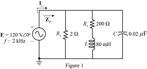
For the network of Fig. 20.50 :
a. Determine the total real, reactive, and apparent power for each parallel branch.
b. Draw the power triangle.
c. Find the total impedance and power factor of the network.
d. Find the source current ls.
Expert Solution & Answer
Want to see the full answer?
Check out a sample textbook solution
Students have asked these similar questions
For the circuit shown in Fig. 2.18, he =1.1 K2, hfe =50. Find Avf, Rif and Rof.
{ Ans: -3.2; 1935; X2807.
Ans:-3-2;193;728. Vcc
Rs=10kQ
RF = 40kQ
Re=4KQ
-ov
Vs
Fig. 2.18 Circuit for Q5.
The circuit of Fig. 2.16 is to have Af=-1mA/V, D=1+ BA = 50, a voltage gain of -4,
Rs =1KQ, and hfe = 150. Find RL, Re, Rif and Rof..
Vcc
www
RL
OV
Ans: 4 kor; 98053150 KS;∞.
{ An
Re
Fig. 2.16 Circuit for Q3.
During the lab you will design and measure a differential amplifier, made with an opamp.
inside generator
R5
ww
500
V1
0.1Vpk
1kHz
0°
R6
w
50Ω
R1
ww
10ΚΩ
VCC
C1
balanced wire
R3
w
15.0V
signal+
100nF U1A
TL082CP
ground
2
signal-
R4
w
C2
Question5: Calculate R3 and R4 for a 20dB.
100nF
VEE
-15.0V
R2
ww
10ΚΩ
Chapter 20 Solutions
Laboratory Manual for Introductory Circuit Analysis
Ch. 20 - For the battery of bulbs (purely resistive)...Ch. 20 - For the network of Fig. 20.49 : a. Find the...Ch. 20 - For the network of Fig. 20.50 : a. Determine the...Ch. 20 - For the system of Fig. 20.51 : a. Find the total...Ch. 20 - For the system of Fig. 20.52 : a. Find PT, QT. and...Ch. 20 - 6. For the system of Fig. 20.53 : a. Find PT, QT....Ch. 20 - For the network of Fig. 20.54 : a. Find the type...Ch. 20 - For the circuit of Fig. 20.55: a. Find the...Ch. 20 - For the network of Fig. 20.56 : a. Find Is. b....Ch. 20 - Repeat Problem 9 for the network of Fig. 20.57.
Ch. 20 - For the network of Fig. 20.58: a. Find the average...Ch. 20 - An electrical system is rated 10 kVA, 200 V at a...Ch. 20 - An electrical system is rated 5 kVA, 120 V, at a...Ch. 20 - For the system of Fig. 20.59: a. Find the total...Ch. 20 - Repeat Problem 14 for the system of Fig. 20.60.Ch. 20 - For the circuit of Fig. 20.61: Find the total...Ch. 20 - For the circuit of Fig. 20.62: Find the total...Ch. 20 - Prob. 18PCh. 20 - The load on a 120 V, 60 Hz supply is 5 kW...Ch. 20 - The loading of a factory on a 1000 V, 60 Hz system...Ch. 20 - a. A wattmeter is connected with its current coil...Ch. 20 - The voltage source in Fig. 20.64 delivers 660 VA...Ch. 20 - a. An air-core coil is connected to a 200 V, 60 Hz...Ch. 20 - a. The inductance of an air-core coil is 0.08 H....Ch. 20 - Using PSpice or Multisim, obtain a plot of...
Additional Engineering Textbook Solutions
Find more solutions based on key concepts
3.3 It is known that a vertical force of 200 lb is required to remove the nail at C from the board. As the nail...
Vector Mechanics for Engineers: Statics
The solid steel shaft AC has a diameter of 25 mm and is supported by smooth bearings at D and E. It is coupled ...
Mechanics of Materials (10th Edition)
1.2 Explain the difference between geodetic and plane
surveys,
Elementary Surveying: An Introduction To Geomatics (15th Edition)
What is an uninitialized variable?
Starting Out with Programming Logic and Design (5th Edition) (What's New in Computer Science)
How is the hydrodynamic entry length defined for flow in a pipe? Is the entry length longer in laminar or turbu...
Fluid Mechanics: Fundamentals and Applications
Using your text editor, enter (that is, type in) the C++ program shown in Display 1.8. Be certain to type the f...
Problem Solving with C++ (10th Edition)
Knowledge Booster


Learn more about
Need a deep-dive on the concept behind this application? Look no further. Learn more about this topic, electrical-engineering and related others by exploring similar questions and additional content below.Similar questions
- not use ai pleasearrow_forward3. Consider the system described by the transfer function Gp(s) polynomial controller to satisfy the below specifications: 1) The settling time is t = 1 second, 2) 0.1% peak overshoot, 3) and zero steady-state error for a ramp input. The sampling period is T = 0.01 second. 1 = Design a discrete-time s(s+5)*arrow_forwardProblem 2 Does there exist a value a that makes the two systems S₁ and S₂ equal? If so, what is this value ? If not, explain why. S₁ x[n] x[n] D D -2 → host 回洄 S with h[m] " 999. усиз -1012345 harrow_forward
- please not use any aiarrow_forwardProblem 2 Does there exist a value a that makes the two systems S₁ and S₂ equal? If so, what is this value ? If not, explain why. S₁ x[n] x[n] D D -2 → host 回洄 S with h[m] " 999. усиз -1012345 harrow_forwardSolve only no 8, Don't use chatgpt or any , only expertarrow_forward
- I need help in creating a matlab code to find the currents USING MARTIXS AND INVERSE to find the currentarrow_forwardQuestion 2 A transistor is used as a switch and the waveforms are shown in Figure 2. The parameters are Vcc = 225 V, VBE(sat) = 3 V, IB = 8 A, VCE(sat) = 2 V, Ics = 90 A, td = 0.5 µs, tr = 1 µs, ts = 3 µs, tƒ = 2 μs, and f 10 kHz. The duty cycle is k 50%. The collector- emitter leakage current is ICEO = 2 mA. Determine the power loss due to the collector current: = = = (a) during turn-on ton = td + tr VCE Vcc (b) during conduction period tn V CE(sat) 0 toff" ton Ics 0.9 Ics (c) during turn-off toff = ts + tf (d) during off-time tot (e) the total average power losses PT ICEO 0 IBS 0 Figure 2 V BE(sat) 0 主 * td tr In Is If to iB VBE T= 1/fsarrow_forwardQuestion 1: The beta (B) of the bipolar transistor shown in Figure 1 varies from 12 to 60. The load resistance is Rc = 5. The dc supply voltage is VCC = 40 V and the input voltage to the base circuit is VB = 5 V. If VCE(sat) = 1.2 V, VBE(sat) = 1.6 V, and RB = 0.8 2, calculate: (a) the overdrive factor ODF. (b) the forced ẞ (c) the power loss in the transistor PT. IB VB RB + V BE RC Vcc' Ic + IE Figure 1 VCEarrow_forward
- I need help in creating a matlab code to find the currentsarrow_forwardI need help fixing this MATLAB code: as I try to get it working there were some problems:arrow_forwardI need help in construct a matlab code to find the voltage of VR1 to VR4, the currents, and the watts based on that circuit.arrow_forward
arrow_back_ios
SEE MORE QUESTIONS
arrow_forward_ios
Recommended textbooks for you
 Power System Analysis and Design (MindTap Course ...Electrical EngineeringISBN:9781305632134Author:J. Duncan Glover, Thomas Overbye, Mulukutla S. SarmaPublisher:Cengage Learning
Power System Analysis and Design (MindTap Course ...
Electrical Engineering
ISBN:9781305632134
Author:J. Duncan Glover, Thomas Overbye, Mulukutla S. Sarma
Publisher:Cengage Learning
Inductors Explained - The basics how inductors work working principle; Author: The Engineering Mindset;https://www.youtube.com/watch?v=KSylo01n5FY;License: Standard Youtube License