
Laboratory Manual for Introductory Circuit Analysis
13th Edition
ISBN: 9780133923780
Author: Robert L. Boylestad, Gabriel Kousourou
Publisher: PEARSON
expand_more
expand_more
format_list_bulleted
Videos
Textbook Question
Chapter 20, Problem 14P
For the system of Fig. 20.59:
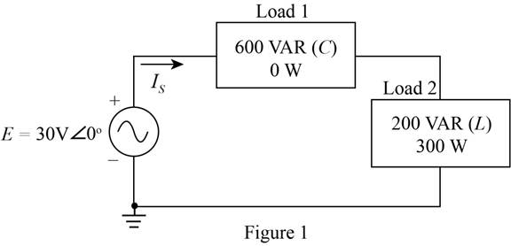
a. Find the total number of watts. volt-amperes reactive, volt-amperes, and Fp.
b. Find the current ls.
c. Draw the power triangle.
d. Find the type of elements and their impedance in ohms within each electrical box. (Assume that all elements of a load are in series.)
e. Verity that the result of part (b) is correct by finding the current ls using only the input voltage E and the results of part (d). Compare the value of ls with that obtained for part (b).
Expert Solution & Answer
Want to see the full answer?
Check out a sample textbook solution
Students have asked these similar questions
1. Compute the output signals S and T for the circuit. Input signals P = 1, Q = 1, and R = 1.
C₁
P
half-adder #1
R
AND
-S
C₁₂
half-adder #2
2. Use 8-bit representations to compute the following sum. Show all work.
57+(-118)
3. Find a counterexample to show that the following statement is false:
1
Vx Є R,
x>-
χ
T
4. Is the proposed negation correct? If yes, provide a sound reasoning. If not, provide a
sound reasoning and write the correct negation.
Statement: For all integers n, if n² is even then n is even.
Negation: For all integers n, if n² is even then n is not even.
not use ai
2. (35 points) Use you program to investigative properties of a four step linear pathway. Just
extend the model given in question 1 to include an additional two species x2 and x3. You can
assume simple irreversible mass-action kinetic on each reaction.
I recommend you use the following values for the rate constants: 1 = 0.6; k2 = 1.8; k3 =
0.5; k40.04. This will enable you to more easily answer the following questions.
You can also assume that the input is the source X and you can set its value to one.
You may find that the plot of the phase change at x3 is broken at -180 degrees because it wraps
around. To avoid this you can use the method:
phase = np.unwrap(phase)
to make sure the phase plot is continuous.
[10] i) Compute and show the Bode plots for x1, x2 and x3 with respect to the input Xo.
[5] ii) Do you see a pattern with the maximum phase shifts as you move from x₁ to x3?
[10] iii) Can you explain this pattern?
[5] iv) What would you predict would be the maximum phase shift for…
Chapter 20 Solutions
Laboratory Manual for Introductory Circuit Analysis
Ch. 20 - For the battery of bulbs (purely resistive)...Ch. 20 - For the network of Fig. 20.49 : a. Find the...Ch. 20 - For the network of Fig. 20.50 : a. Determine the...Ch. 20 - For the system of Fig. 20.51 : a. Find the total...Ch. 20 - For the system of Fig. 20.52 : a. Find PT, QT. and...Ch. 20 - 6. For the system of Fig. 20.53 : a. Find PT, QT....Ch. 20 - For the network of Fig. 20.54 : a. Find the type...Ch. 20 - For the circuit of Fig. 20.55: a. Find the...Ch. 20 - For the network of Fig. 20.56 : a. Find Is. b....Ch. 20 - Repeat Problem 9 for the network of Fig. 20.57.
Ch. 20 - For the network of Fig. 20.58: a. Find the average...Ch. 20 - An electrical system is rated 10 kVA, 200 V at a...Ch. 20 - An electrical system is rated 5 kVA, 120 V, at a...Ch. 20 - For the system of Fig. 20.59: a. Find the total...Ch. 20 - Repeat Problem 14 for the system of Fig. 20.60.Ch. 20 - For the circuit of Fig. 20.61: Find the total...Ch. 20 - For the circuit of Fig. 20.62: Find the total...Ch. 20 - Prob. 18PCh. 20 - The load on a 120 V, 60 Hz supply is 5 kW...Ch. 20 - The loading of a factory on a 1000 V, 60 Hz system...Ch. 20 - a. A wattmeter is connected with its current coil...Ch. 20 - The voltage source in Fig. 20.64 delivers 660 VA...Ch. 20 - a. An air-core coil is connected to a 200 V, 60 Hz...Ch. 20 - a. The inductance of an air-core coil is 0.08 H....Ch. 20 - Using PSpice or Multisim, obtain a plot of...
Knowledge Booster


Learn more about
Need a deep-dive on the concept behind this application? Look no further. Learn more about this topic, electrical-engineering and related others by exploring similar questions and additional content below.Similar questions
- Please answer all The zombies showed up while you were sleeping! The zombie alarm you built goes off as they open the door. You jolt awake to see an alpha-zombie charging through the door. The alphas are zombies that turned all of the zombies in its army. If you can take down this one zombie, all the others pouring into the room should fall as well. Luckily, your group was prepared for this eventuality. Another member of your team has constructed the zombie shocker circuit shown in Figure 5, using some batteries for the voltage source, some rusty metal for the resistors and a coil of wire for the inductor. The switch is just you pulling apart two wires to open the circuit (while holding them by their insulated sheaths). 1. Construct the circuit shown in Figure 15 in the Circuit JS simulator. 2. Start the simulation with switch SW1 in the closed position. You’ve been charging this circuit all night, so you’ll want to let the circuit run for a while (roughly 30 seconds at max…arrow_forwardPlease answer all questions 1. Calculate the values of the following without using Circuit JS. Assume the circuit has reached steady state. Show these calculations: a) Voltage across and current through C1. b) Voltage across and current through L1. c) Voltage across and current through R5. 2. Construct the circuit in the Circuit JS simulator [1]. 3. Perform a simulation and determine the following values. Record them. Allow the circuit to reach steady state. a) Voltage across and current through C1. b) Voltage across and current through L1. c) Voltage across and current through R5. 4. Include a screen shot of the simulator window (including showing the values listed above). 5. Answer the following questions: a) In a DC circuit, what does a capacitor look like? b) In a DC circuit, what does an inductor look like?arrow_forwardHelp with homework, with the extra portion part too pleasearrow_forward
- Redraw the previous circuit and add a 24 V red lamp to indicate the relay coil is on, a 230 V yellow lamp to indicate the solenoid is on, green lamp to indicate the solenoid is off. Use only one relay, which has multiple contacts.arrow_forwardDesign a control circuit so a 24 V relay , start button, and a stop push button (on/off with memory) operates an electromechanical relay to control a 230 V solenoid Next, Redraw the previous circuit and add a 24 V red lamp to indicate the relay coil is on, a 230 V yellow lamp to indicate the solenoid is on, green lamp to indicate the solenoid is off. Use only one relay, which has multiple contacts.arrow_forwardplease answer it handwritten , thanks! will give thumbs uparrow_forward
- EXAMPLE 6.3 Suppose the Fourier transform of a pulse is as follows: (1-a) Ть. 2Ть H(f) = < α (To) (-Tof+ 1 +a (1-a) (1+α) ·<|f|≤· 2 2ть 2Ть (1+α) 0, <\f\ 2Ть where 0≤a≤1. Show that this pulse in both time and frequency domains satisfies the Nyquist criterion.arrow_forwardIn matlabarrow_forwardnot use ai pleasearrow_forward
- In matlabarrow_forwardEXAMPLE 4.4 In a binary symmetric communication (BSC) channel, the input bits transmitted over the channel are either 0 or 1 with probabilities p and 1-p, respectively. Due to channel noise, errors are made. As shown in Figure 4.4, the channel is assumed to be symmetric, which means the probability of receiving 1 when 0 is transmitted is the same as the probability of receiving 0 when 1 is transmit- ted. The conditional probabilities of error are assumed to be each e. Determine the average prob- ability of error, also known as the bit error rate, as well as the a posteriori probabilities.arrow_forwardWhat is the bandwidth requirement in Hz for baseband binary transmission at 64 kbps, if the roll-off factor is 0.25?arrow_forward
arrow_back_ios
SEE MORE QUESTIONS
arrow_forward_ios
Recommended textbooks for you
 Introductory Circuit Analysis (13th Edition)Electrical EngineeringISBN:9780133923605Author:Robert L. BoylestadPublisher:PEARSON
 Delmar's Standard Textbook Of ElectricityElectrical EngineeringISBN:9781337900348Author:Stephen L. HermanPublisher:Cengage Learning
 Programmable Logic ControllersElectrical EngineeringISBN:9780073373843Author:Frank D. PetruzellaPublisher:McGraw-Hill Education
 Fundamentals of Electric CircuitsElectrical EngineeringISBN:9780078028229Author:Charles K Alexander, Matthew SadikuPublisher:McGraw-Hill Education
 Electric Circuits. (11th Edition)Electrical EngineeringISBN:9780134746968Author:James W. Nilsson, Susan RiedelPublisher:PEARSON
 Engineering ElectromagneticsElectrical EngineeringISBN:9780078028151Author:Hayt, William H. (william Hart), Jr, BUCK, John A.Publisher:Mcgraw-hill Education,
Introductory Circuit Analysis (13th Edition)
Electrical Engineering
ISBN:9780133923605
Author:Robert L. Boylestad
Publisher:PEARSON
Delmar's Standard Textbook Of Electricity
Electrical Engineering
ISBN:9781337900348
Author:Stephen L. Herman
Publisher:Cengage Learning
Programmable Logic Controllers
Electrical Engineering
ISBN:9780073373843
Author:Frank D. Petruzella
Publisher:McGraw-Hill Education
Fundamentals of Electric Circuits
Electrical Engineering
ISBN:9780078028229
Author:Charles K Alexander, Matthew Sadiku
Publisher:McGraw-Hill Education
Electric Circuits. (11th Edition)
Electrical Engineering
ISBN:9780134746968
Author:James W. Nilsson, Susan Riedel
Publisher:PEARSON
Engineering Electromagnetics
Electrical Engineering
ISBN:9780078028151
Author:Hayt, William H. (william Hart), Jr, BUCK, John A.
Publisher:Mcgraw-hill Education,
Inductors Explained - The basics how inductors work working principle; Author: The Engineering Mindset;https://www.youtube.com/watch?v=KSylo01n5FY;License: Standard Youtube License