
Electrical Engineering: Principles & Applications, Student Value Edition Plus Mastering Engineering with Pearson eText -- Access Card Package (7th Edition)
7th Edition
ISBN: 9780134702193
Author: Allan R. Hambley
Publisher: PEARSON
expand_more
expand_more
format_list_bulleted
Concept explainers
Videos
Textbook Question
Chapter 2, Problem 2.8P
- Determine the resistance between terminals a and b for the network shown in Figure P2.8.
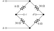
Figure P2.8
Expert Solution & Answer

Trending nowThis is a popular solution!

Students have asked these similar questions
The solution is with a pen and paper, without artificial intelligence.
Q5 For the network of Fig. 1.42; determine re, Avmid, Zi, Avsmid, and the low cutoff frequency.
Ans: 30.23 2; 0.983; 21.13 KS; 0.955; 193.16 Hz.
14V
+
Vs
1 ΚΩ
0.1 µF
Vi
120 ΚΩ
B-100
0.1 µF
o Vo
30 ΚΩ
32.2 ΚΩ
18.2 ΚΩ
Fig. 1.42 Circuit for Q5.
31
Q1) (a) State Biot-Savart's law
(b) The y- and z-axes, respectively, carry filamentary currents 10 A along ay
and 20 A along -az. Find H at (- 3, 4, 5).
Chapter 2 Solutions
Electrical Engineering: Principles & Applications, Student Value Edition Plus Mastering Engineering with Pearson eText -- Access Card Package (7th Edition)
Ch. 2 - Reduce each of the networks shown in Figure P2.1...Ch. 2 - A 4- resistance is in series with the parallel...Ch. 2 - Find the equivalent resistance looking into...Ch. 2 - Suppose that we need a resistance of 1.5 k and...Ch. 2 - Find the equivalent resistance between terminals a...Ch. 2 - Find the equivalent resistance between terminals a...Ch. 2 - What resistance in parallel with 120 results in...Ch. 2 - Determine the resistance between terminals a and b...Ch. 2 - Two resistances having values of R and 2R are in...Ch. 2 - A network connected between terminals a and b...
Ch. 2 - Two resistances R1 and R2 are connected in...Ch. 2 - Find the equivalent resistance for the infinite...Ch. 2 - If we connect n 1000- resistances in parallel,...Ch. 2 - The heating element of an electric cook top has...Ch. 2 - We are designing an electric space heater to...Ch. 2 - Sometimes, we can use symmetry considerations to...Ch. 2 - The equivalent resistance between terminals a and...Ch. 2 - Three conductances G1 G2, and G3 are in series....Ch. 2 - Most sources of electrical power behave as...Ch. 2 - The resistance for the network shown in Figure...Ch. 2 - Often, we encounter delta-connected loads such as...Ch. 2 - What are the steps in solving a circuit by network...Ch. 2 - Find the values of i1 and i2 in Figure P2.23....Ch. 2 - Find the voltages v1 and v2 for the circuit shown...Ch. 2 - Find the values of v and i in Figure P2.25. Figure...Ch. 2 - Consider the circuit shown in Figure P2.24....Ch. 2 - Find the voltage v and the currents i1 and 12 for...Ch. 2 - Find the values of vs, v1, and i2 in Figure P2.28....Ch. 2 - Find the values of i1 and i2 in Figure P2.29....Ch. 2 - Consider the cirrcuit shown in Figure P2.30 Find...Ch. 2 - Solve for the values of i1, i2, and the powers for...Ch. 2 - The 12-V source in Figure P2.32 is delivering 36...Ch. 2 - Refer to the circuit shown in Figure P2.33. With...Ch. 2 - Find the values of i1 and i2 in Figure P2.34. Find...Ch. 2 - Find the values of i1 and i2 in Figure P2.35...Ch. 2 - Use the voltage-division principle to calculate...Ch. 2 - Use the current-division principle to calculate i1...Ch. 2 - Use the voltage-division principle to calculate...Ch. 2 - Use the current-division principle to calculate...Ch. 2 - Suppose we need to design a voltage-divider...Ch. 2 - A source supplies 120 V to the series combination...Ch. 2 - We have a 60- resistance, a 20- resistance, and...Ch. 2 - A worker is standing on a wet concrete floor,...Ch. 2 - Suppose we have a load that absorbs power and...Ch. 2 - We have a load resistance of 50 that we wish to...Ch. 2 - We have a load resistance of 1 k that we wish to...Ch. 2 - The circuit of Figure P2.47 is similar to networks...Ch. 2 - Write equations and solve for the node voltages...Ch. 2 - Solve for the node voltages shown in Figure P2.49....Ch. 2 - Solve for the node voltages shown in Figure P2.50....Ch. 2 - Given R1=4 , R2=5 , R2=8 , R4=10 , R5=2 , and...Ch. 2 - Determine the value of i1 in Figure P2.52 using...Ch. 2 - Given R1=15 , R5=5 , R3=20 , R4=10 , R5=8 , R6=4 ,...Ch. 2 - In solving a network, what rule must you observe...Ch. 2 - Use the symbolic features of MATLAB to find an...Ch. 2 - Solve for the values of the node voltages shown in...Ch. 2 - Solve for the node voltages shown in Figure P2.57....Ch. 2 - Solve for the power delivered to the 8- ...Ch. 2 - Solve for the node voltages shown in Figure P2.59....Ch. 2 - Find the equivalent resistance looking into...Ch. 2 - Find the equivalent resistance looking into...Ch. 2 - Figure P2.62 shows an unusual voltage-divider...Ch. 2 - Solve for the node voltages in the circuit of...Ch. 2 - We have a cube with 1- resistances along each...Ch. 2 - Solve for the power delivered to the 15- resistor...Ch. 2 - Determine the value of v2 and the power delivered...Ch. 2 - Use mesh-current analysis to find the value of i1...Ch. 2 - Solve for the power delivered by the voltage...Ch. 2 - Use mesh-current analysis to find the value of v...Ch. 2 - Use mesh-current analysis to find the value of i3...Ch. 2 - Use mesh-current analysis to find the values of i1...Ch. 2 - Find the power delivered by the source and the...Ch. 2 - Use mesh-current analysis to find the values of i1...Ch. 2 - Use mesh-current analysis to find the values of i1...Ch. 2 - The circuit shown in Figure P2.75 is the dc...Ch. 2 - Use MATLAB and mesh-current analysis to determine...Ch. 2 - Connect a 1-V voltage source across terminals a...Ch. 2 - Connect a 1-V voltage source across the terminals...Ch. 2 - Use MATLAB to solve for the mesh currents in...Ch. 2 - Find the Thévenin and Norton equivalent circuits...Ch. 2 - We can model a certain battery as a voltage source...Ch. 2 - Find the Thévenin and Norton equivalent circuits...Ch. 2 - Find the Thévenin and Norton equivalent circuits...Ch. 2 - Find the Thévenin arid Norton equivalent circuits...Ch. 2 - An automotive battery has an open-circuit voltage...Ch. 2 - A certain two-terminal circuit has an open-circuit...Ch. 2 - If we measure the voltage at the terminals of a...Ch. 2 - Find the Thévenin and Norton equivalent circuits...Ch. 2 - Find the maximum power that can be delivered to a...Ch. 2 - Find the maximum power that can be delivered to a...Ch. 2 - Figure P2.91 shows a resistive load RL connected...Ch. 2 - Starling from the Norton equivalent circuit with a...Ch. 2 - A battery can be modeled by a voltage source Vt in...Ch. 2 - Use superposition to find the current i in Figure...Ch. 2 - Solve for is in Figure P2.49 by using...Ch. 2 - Solve the circuit shown in Figure P2.48 by using...Ch. 2 - Solve for i1 in Figure P2.34 by using...Ch. 2 - Another method of solving the circuit of Figure...Ch. 2 - Use the method of Problem P2.98 for the circuit of...Ch. 2 - Solve for the actual value of i6 for the circuit...Ch. 2 - Device A shown in Figure P2.101 has v=3i2 for i 0...Ch. 2 - The Wheatstone bridge shown in Figure 2.66 is...Ch. 2 - The Wheatstone bridge shown in Figure 2.66has...Ch. 2 - In theory, any values can be used for R1 and R3 in...Ch. 2 - Derive expressions for the Thévenin voltage and...Ch. 2 - Derive Equation 2.93 for the bridge circuit of...Ch. 2 - Prob. 2.107PCh. 2 - Explain what would happen if, in wiring the bridge...Ch. 2 - Match each entry in Table T2.1(a) with the best...Ch. 2 - Consider the circuit of Figure T2.2 with vs=96V ,...Ch. 2 - Write MATLAB code to solve for the node voltages...Ch. 2 - Write a set of equations that can be used to solve...Ch. 2 - Determine the Thévenin and Norton equivalent...Ch. 2 - According to the superposition principle, what...Ch. 2 - Determine the equivalent resistance between...Ch. 2 - Transform the 2-A current source and 6- ...
Knowledge Booster


Learn more about
Need a deep-dive on the concept behind this application? Look no further. Learn more about this topic, electrical-engineering and related others by exploring similar questions and additional content below.Similar questions
- Q5) a) State Ampere's circuit law. b) In a certain conducting region, H = yz(x² + y²)ax - y²xzay + 4x²y²a, A/m. (a) Determine J at (5, 2, -3) (b) Find the current passing through x = -1, 0 < y, z <2 (c) Show that V⚫H=0arrow_forwardFig. 1.43 Circuit for Q6- Q7 For the network of Fig. 1.44: a-Determine fH; and fHo b- Find fg and fr. c- Sketch the frequency response for the high-frequency region using a Bode plot and determine the cutoff frequency. Ans: 277.89 KHz; 2.73 MHz; 895.56 KHz; 107.47 MHz. 14V Cw=5pF Cbc-12 pF Cwo-8pF Che=40. pF 5.6kQ C-8pF 68kQ 0.47µF ww 0.82 kQ V₁ 0.47uF AN B=120 3.3kQ 10ΚΩ 1.2k0 =20µF Fig. 1.44 Circuit for Q7.arrow_forwardQ3) An infinite long filamentary wire carries a current of 2A in the +z direction. calculate: (a)B at (-3,4,7) (b) the flux through the square loop described by 25 16,0 Sz≤4, 0=90°.arrow_forward
- Q3) An infinitely long conductor is bent into an L shape as shown in Figure below. If a direct current of 5 A flows in the current, find the magnetic field intensity at (2, 2, 0). 5 A 5 Aarrow_forwardEx. 1° let Ĥ = -y (x²+y^³) ax + x (x²+y"`) ây":" H 5 find J M total current Passing through Z=oplane with the rectangular -\-2<<2arrow_forwardQ) Given the magnetic field vector potential: A= y² za, +2(x+1)y z ay- (x+1) z² az (A/m), find: (1)magnetic flux density B, (2)magnetic field intensity H, (3) current density J and (4) the current passing through surface y = 1,0≤x≤1, 0 ≤z≤1.arrow_forward
- Q9 For the network of Fig. 1.46: a- Determine gmo and gm. b- Find A, and Ay, in the mid-frequency range. c- Determine fH; and fHo Ans: 3.33 mS; 1.91 mS; -4.39; -4.27; 1.84 MHz; 3.68 MHz. + 1.5 kQ 20V 3220ΚΩ 1µF 68kQ AN CwF4pF Co=8 pF Cwo=6pF Cgs=12pF 53.9ΚΩ Cds=3pF 6.8µF o Vo Dss=10mA Vp=-6V 15.6 ΚΩ 2.2k =10µF Fiarrow_forwardQs For the network of Fig. 1.45: a- Determine fH, and fHo b- Find fp and fr c- Sketch the frequency response for the high-frequency region using a Bode plot and determine the cutoff frequency. Ans: 2.87 MHz, 185.78 MHz, 1.05 MHz, 105 MHz. 14V CWF8pF Cwo-10pF Cbc-20 pF Cbe=30pF 120 ΚΩ Co=12pF 1 ΚΩ B-100 0.1 µF Vs 0.1 HF Z; Vo www 30 kQ 2.2 ΚΩ € 8.2 kQ Fig. 1.45 Circuit for Carrow_forward5 A Q4) A thin ring of radius 5 cm is placed on plane z = 1 cm so that its center is at (0,0,1 cm). If the ring carries 50 mA along a^, find H at (0,0,a).arrow_forward
- Q6) Find the current density J for the magnetic field intensity vectors: (a) H = x²ya, + y²zay - 2xza, (b) H = p²zap + p³a + 3pz²az sin cos (c) H = a, 2 +2arrow_forwardQ2) Line x = 0, y=0,0arrow_forwardQ4) Given the magnetic vector potential: A = y²z ax-(x + 1)z² az A/m Find(a) the magnetic flux density; (b)the magnetic flux through a square loop described by 0≤x≤1, 0 ≤ y ≤1, z=2.arrow_forwardarrow_back_iosSEE MORE QUESTIONSarrow_forward_ios
Recommended textbooks for you
 Delmar's Standard Textbook Of ElectricityElectrical EngineeringISBN:9781337900348Author:Stephen L. HermanPublisher:Cengage Learning
Delmar's Standard Textbook Of Electricity
Electrical Engineering
ISBN:9781337900348
Author:Stephen L. Herman
Publisher:Cengage Learning
Star Delta Starter Explained - Working Principle; Author: The Engineering Mindset;https://www.youtube.com/watch?v=h89TTwlNnpY;License: Standard Youtube License