
Concept explainers
Videos
The current waveform depicted in Fig. 2.29 is characterized by a period of 4 s. (a) What is the average value of the current over a single period? (b) Compute the average current over the interval 1 < t < 3 s. (c) If q(0) = 1C, sketch q(t), 0 < t < 4 s.
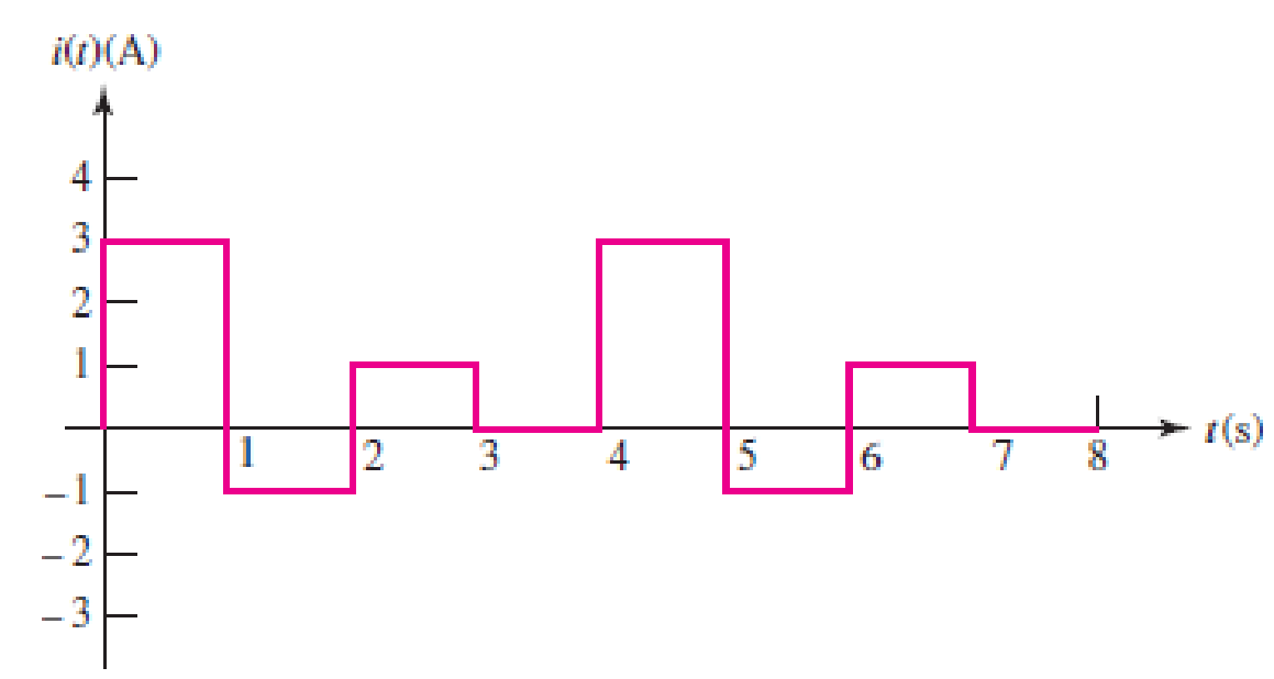
FIGURE 2.29 An example of a time-varying current.
(a)
Find the average value of the given current waveform in Figure 2.29 over the period of 4 s.
Answer to Problem 21E
The average value of the given current waveform over the period of 4 s is
Explanation of Solution
Given data:
Refer to Figure 2.29 in textbook for the time-varying current with the period of 4 s.
Formula used:
Write the formula to find the average value of a function of current over a period as,
Here,
T is the time period.
Calculation:
From the given current waveform in Figure 2.29, the function of current
For the period of
For the period of
For the period of
For the period of
Therefore, the final function of current
The average value of current
Reduce the equation as follows.
Conclusion:
Thus, the average value of the given current waveform over the period of 4 s is
(b)
Find the average current of the waveform over the period of
Answer to Problem 21E
The average current of the waveform over the period of
Explanation of Solution
Given data:
Refer to part (a).
Formula used:
Write the formula to find the average value of a function of current over a period of
Here,
Calculation:
Write the function of current
Now, the average current of
Conclusion:
Thus, the average current of the waveform over the period of
(c)
Sketch the waveform for the charge
Explanation of Solution
Given data:
Refer to part (a).
The initial charge
Formula used:
Write the expression for the relation between charge
Integrate the above equation on both sides.
Calculation:
Using the function of
For
Substitute 3 A for
Substitute 1 C for
Substitute 1 for
For
For the period of
Substitute –1 A for
Substitute 4 C for
Substitute 2 for
For
For the period of
Substitute 1 A for
Substitute 3 C for
Substitute 3 for
For
For the period of
Substitute 0 A for
Substitute 4 C for
Therefore, the charge
Table 1 shows for
Table 1
| t in seconds | |
| 0 | 1 |
| 1 | 4 |
| 2 | 2 |
| 3 | 4 |
| 4 | 4 |
Figure 1 shows the charge (C) vs time (s) waveform.
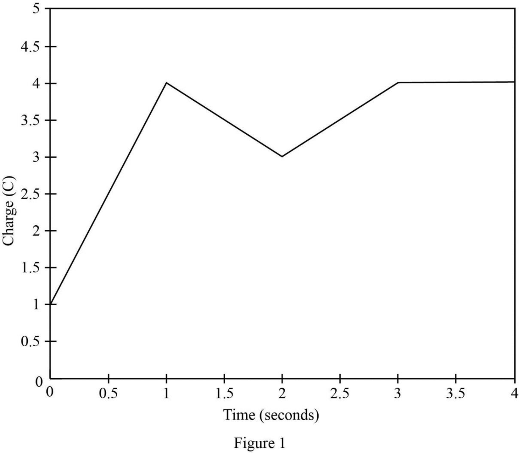
Conclusion:
Thus, the waveform for the charge
Want to see more full solutions like this?
Chapter 2 Solutions
ENGINEERING CIRCUIT...(LL)>CUSTOM PKG.<


- istics of diodes, bipolar junction transistors, and plain the structure, operation, 1. The purpose of doping in semiconductor diodes is: a) To control their electrical properties b) To increase their physical size c) To enhance their mechanical strength d) To improve their thermal stability 2. In electronics production, your team wants to manufacture a very cheap diode rectifier. Which of the following rectifier configurations would you select? a) Half-wave rectifier c) Full-wave rectifier b) Bridge rectifier d) Controlled rectifier 3. The region that a Zener diode operates to provide voltage regulation is: a) Saturation c) Reverse bias b) Breakdown d) Forward bias 4. In NMOS transistors, the depth of the channel is primarily changed by: a) VDS b) lp c) VGS d) None of these 5. NMOS transistors have than PMOS, resulting in better current conduction: b) Long channel a) High mobility c) Low mobility d) Short channel 6. You are working in electronic production, and your team is asked to…arrow_forward8.46 The generator circuit shown in Fig. P8.46 (on page 494) isconnected to a distant load via a long coaxial transmission line.The overall circuit can be modeled as in Fig. P8.46(b), in whichthe transmission line is represented by an equivalent impedanceZline = (5+ j2) W.(a) Determine the power factor of voltage source Vs.(b) Specify the capacitance of a shunt capacitor C that wouldraise the power factor of the source to unity when connectedbetween terminals (a,b). The source frequency is 1.5 kHz.arrow_forward7. MOSFET circuit The MOSFET in the circuit below has V₁ = 1 V and kn = 4 mA/V². a) Is the MOSFET operating in saturation or in the triode region? b) Determine the drain current ID and Vout. + 5 V 5 k Voutarrow_forward
- Draw a logic diagram of a 4-bit adder/subtractor then use it to design an Exess-3 to BCD code converter circuit. The circuit has an input (x4 xs x2x) and output (ye ya ya yi)scrarrow_forwardIf waveforms shown in figure below are applied as inputs to a 2-bit comparator (P=P: Po and Q=Q: Q), draw the three output waveforms of the comparator (P>Q, P=Q, Parrow_forwardmicro wavearrow_forwardmicro wavearrow_forwardFor this question, please show how to get the answer using block diagrams. I have included my attempt but I am not close to the answer and I don't understand how to get the T_d(s) expression. Please show the block diagram steps, as in, do not just plug this question into an AI. thank youarrow_forwardOnly expert should attempt this questions, handwritten solution onlyarrow_forwardarrow_back_iosSEE MORE QUESTIONSarrow_forward_ios
 Introductory Circuit Analysis (13th Edition)Electrical EngineeringISBN:9780133923605Author:Robert L. BoylestadPublisher:PEARSON
 Delmar's Standard Textbook Of ElectricityElectrical EngineeringISBN:9781337900348Author:Stephen L. HermanPublisher:Cengage Learning
 Programmable Logic ControllersElectrical EngineeringISBN:9780073373843Author:Frank D. PetruzellaPublisher:McGraw-Hill Education
 Fundamentals of Electric CircuitsElectrical EngineeringISBN:9780078028229Author:Charles K Alexander, Matthew SadikuPublisher:McGraw-Hill Education
 Electric Circuits. (11th Edition)Electrical EngineeringISBN:9780134746968Author:James W. Nilsson, Susan RiedelPublisher:PEARSON
 Engineering ElectromagneticsElectrical EngineeringISBN:9780078028151Author:Hayt, William H. (william Hart), Jr, BUCK, John A.Publisher:Mcgraw-hill Education,