
Concept explainers
Videos
(a)
The magnitude and direction of the magnetic field due to wire 1 at the location of wire 2.
(a)
Answer to Problem 79P
The magnetic field due to wire 1 at the location of wire 2 is
Explanation of Solution
Given that the separation between wires is
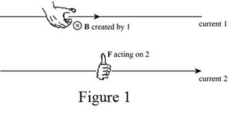
The direction of the magnetic field produced by wire 1 can be determined by the right-hand rule 2. By placing the thumb along the current
Write the expression for the magnitude of magnetic field at a distance
Here,
Conclusion:
From Figure 1, the use of right-hand rule 2 results, the direction of magnetic field due to wire 1 at the location of wire 2 perpendicular to the plane of the wires.
Apply the equation (I) to the given system to obtain the expression for the magnitude of the magnetic field due to wire 1 at the location of wire 2.
Write the magnetic field due to wire 1 at the location of wire 2 including magnitude and direction.
Therefore, the magnetic field due to wire 1 at the location of wire 2 is
(b)
The magnitude and direction of the magnetic force on wire 2.
(b)
Answer to Problem 79P
The magnetic force on wire 2 is
Explanation of Solution
Given that the separation between wires is
The direction of the magnetic force on wire 2 can be determined by the right-hand rule 2 as shown in Figure 1.
Write the expression for the magnetic force due to a current carrying wire.
Here,
Conclusion:
From Figure 1, the use of right-hand rule 2 results, the direction of magnetic force on wire 2 towards the current
Apply the equation (II) to the given system to obtain the expression for the magnetic force on wire 2.
Use expression for
Therefore, the magnetic force on wire 2 is
(c)
The magnitude and direction of the magnetic field due to wire 2 at the location of wire 1.
(c)
Answer to Problem 79P
The magnetic field due to wire 2 at the location of wire 1 is
Explanation of Solution
Given that the separation between wires is
The direction of the magnetic field produced by wire 2 can be determined by the right-hand rule 2. By placing the thumb along the current
Equation (I) gives expression for the magnitude of magnetic field at a distance
Conclusion:
The use of right-hand rule 2 results, the direction of magnetic field due to wire 2 at the location of wire 1 perpendicular to the plane of the wires and opposite to
Apply the equation (I) to the given system to obtain the expression for the magnitude of the magnetic field due to wire 2 at the location of wire 1.
Write the magnetic field due to wire 2 at the location of wire 1 including magnitude and direction.
Therefore, the magnetic field due to wire 2 at the location of wire 1 is
(d)
The magnitude and direction of the magnetic force on wire 1.
(d)
Answer to Problem 79P
The magnetic force on wire 1 is
Explanation of Solution
Given that the separation between wires is
The direction of the magnetic force on wire 1 can be determined by the right-hand rule 2 similar as done in part (b).
Equation (II) gives the expression for the magnetic force due to a current carrying wire.
Conclusion:
The use of right-hand rule 2 results, the direction of magnetic force on wire 1 towards the current
Apply the equation (II) to the given system to obtain the expression for the magnetic force on wire 1.
Use expression for
Therefore, the magnetic force on wire 1 is
(e)
Whether the parallel currents in the same direction attract or repel, and whether the parallel currents in opposite direction attract or repel.
(e)
Answer to Problem 79P
The parallel currents in the same direction
Explanation of Solution
The magnetic force is determined from the cross product of the length (along the current direction) and the magnetic field. If the currents in the parallel wires are in the same direction, the forces will be attractive in nature.
Reversing the current’s direction causes the cross products to be oppositely directed. This causes the force on each wire is away from the other wire. Thus, antiparallel currents repels.
Conclusion:
Therefore, the parallel currents in the same direction
(f)
Whether the magnitudes and directions of the magnetic force due to the current carrying wires are consistent with
(f)
Answer to Problem 79P
The magnitudes and directions of the magnetic force due to the current carrying wires are consistent with Newton’s third law.
Explanation of Solution
The forces on the two currents are equal in magnitude and opposite in direction. According to Newton’s third law, for every action there is an equal and opposite reaction. In the case of current passing through the parallel wires, the forces can be identified as one opposes the other but equal in magnitude.
Both the parallel currents and antiparallel currents are consistent with Newton’s third law, since the forces on the two currents are equal and opposite in direction.
Conclusion:
Therefore, the magnitudes and directions of the magnetic force due to the current carrying wires are consistent with Newton’s third law.
Want to see more full solutions like this?
Chapter 19 Solutions
Physics


- Sketch the harmonic on graphing paper.arrow_forwardExercise 1: (a) Using the explicit formulae derived in the lectures for the (2j+1) × (2j + 1) repre- sentation matrices Dm'm, (J/h), derive the 3 × 3 matrices corresponding to the case j = 1. (b) Verify that they satisfy the so(3) Lie algebra commutation relation: [D(Î₁/ħ), D(Î₂/h)]m'm₁ = iƊm'm² (Ĵ3/h). (c) Prove the identity 3 Dm'm,(β) = Σ (D(Ρ)D(Ρ))m'¡m; · i=1arrow_forwardSketch the harmonic.arrow_forward
- For number 11 please sketch the harmonic on graphing paper.arrow_forward# E 94 20 13. Time a) What is the frequency of the above wave? b) What is the period? c) Highlight the second cycle d) Sketch the sine wave of the second harmonic of this wave % 7 & 5 6 7 8 * ∞ Y U 9 0 0 P 150arrow_forwardShow work using graphing paperarrow_forward
- Can someone help me answer this physics 2 questions. Thank you.arrow_forwardFour capacitors are connected as shown in the figure below. (Let C = 12.0 μF.) a C 3.00 με Hh. 6.00 με 20.0 με HE (a) Find the equivalent capacitance between points a and b. 5.92 HF (b) Calculate the charge on each capacitor, taking AV ab = 16.0 V. 20.0 uF capacitor 94.7 6.00 uF capacitor 67.6 32.14 3.00 µF capacitor capacitor C ☑ με με The 3 µF and 12.0 uF capacitors are in series and that combination is in parallel with the 6 μF capacitor. What quantity is the same for capacitors in parallel? μC 32.14 ☑ You are correct that the charge on this capacitor will be the same as the charge on the 3 μF capacitor. μCarrow_forwardIn the pivot assignment, we observed waves moving on a string stretched by hanging weights. We noticed that certain frequencies produced standing waves. One such situation is shown below: 0 ст Direct Measurement ©2015 Peter Bohacek I. 20 0 cm 10 20 30 40 50 60 70 80 90 100 Which Harmonic is this? Do NOT include units! What is the wavelength of this wave in cm with only no decimal places? If the speed of this wave is 2500 cm/s, what is the frequency of this harmonic (in Hz, with NO decimal places)?arrow_forward
- Four capacitors are connected as shown in the figure below. (Let C = 12.0 µF.) A circuit consists of four capacitors. It begins at point a before the wire splits in two directions. On the upper split, there is a capacitor C followed by a 3.00 µF capacitor. On the lower split, there is a 6.00 µF capacitor. The two splits reconnect and are followed by a 20.0 µF capacitor, which is then followed by point b. (a) Find the equivalent capacitance between points a and b. µF(b) Calculate the charge on each capacitor, taking ΔVab = 16.0 V. 20.0 µF capacitor µC 6.00 µF capacitor µC 3.00 µF capacitor µC capacitor C µCarrow_forwardTwo conductors having net charges of +14.0 µC and -14.0 µC have a potential difference of 14.0 V between them. (a) Determine the capacitance of the system. F (b) What is the potential difference between the two conductors if the charges on each are increased to +196.0 µC and -196.0 µC? Varrow_forwardPlease see the attached image and answer the set of questions with proof.arrow_forward
 College PhysicsPhysicsISBN:9781305952300Author:Raymond A. Serway, Chris VuillePublisher:Cengage Learning
 University Physics (14th Edition)PhysicsISBN:9780133969290Author:Hugh D. Young, Roger A. FreedmanPublisher:PEARSON
 Introduction To Quantum MechanicsPhysicsISBN:9781107189638Author:Griffiths, David J., Schroeter, Darrell F.Publisher:Cambridge University Press
 Physics for Scientists and EngineersPhysicsISBN:9781337553278Author:Raymond A. Serway, John W. JewettPublisher:Cengage Learning
 Lecture- Tutorials for Introductory AstronomyPhysicsISBN:9780321820464Author:Edward E. Prather, Tim P. Slater, Jeff P. Adams, Gina BrissendenPublisher:Addison-Wesley
 College Physics: A Strategic Approach (4th Editio...PhysicsISBN:9780134609034Author:Randall D. Knight (Professor Emeritus), Brian Jones, Stuart FieldPublisher:PEARSON