
Concept explainers
Videos
(a)
The magnetic force on each side of the loop.
(a)
Answer to Problem 52P
The magnetic force on each side of the loop is given in table 1.
Explanation of Solution
Refer figure 1.
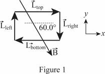
Write an expression for the force on the side.
F=ILBsinθ (I)
Here,F is the magnitude of the force, I is the magnitude of the current, L is the length of the wire, B is the magnitude of magnetic field and θ is the angle.
Conclusion:
Consider the top side of the loop:
Substitute 1.0 A for I, 30.0 cm for L, 2.5 T for B and 60.0° for θ in equation (I) to find F.
F=(1.0 A)((30.0 cm)(1 m102 cm))(2.5 T)sin(60.0°)=(1.0 A)(0.300 m)(2.5 T)sin(60.0°)=0.65 N
Consider the right side of the loop:
Substitute 1.0 A for I, 20.0 cm for L, 2.5 T for B and 30.0° for θ in equation (I) to find F.
F=(1.0 A)((20.0 cm)(1 m102 cm))(2.5 T)sin(30.0°)=(1.0 A)(0.200 m)(2.5 T)sin(30.0°)=0.25 N
Consider the bottom side of the loop:
Substitute 1.0 A for I, 30.0 cm for L, 2.5 T for B and 120° for θ in equation (I) to find F.
F=(1.0 A)((30.0 cm)(1 m102 cm))(2.5 T)sin(120°)=(1.0 A)(0.300 m)(2.5 T)sin(120°)=0.65 N
Consider the left side of the loop:
Substitute 1.0 A for I, 20.0 cm for L, 2.5 T for B and 150° for θ in equation (I) to find F.
F=(1.0 A)((20.0 cm)(1 m102 cm))(2.5 T)sin(150°)=(1.0 A)(0.200 m)(2.5 T)sin(150°)=0.25 N
According to right hand rule, if the thumb, index finger and middle finger are kept perpendicular to each other, the thumb points towards the direction of force if the index finger is kept along the magnetic field and the middle finger is kept along the direction of current.
Thus, the magnetic force on each side of the loop is given in table 1.
| Side | →L | θ | F(N) | Direction of →F |
| Top | 0.300 m right | 60.0° | 0.65 | Into the page |
| Right | 0.200 m down | 30.0° | 0.25 | Out of the page |
| Bottom | 0.300 m right | 120° | 0.65 | Out of the page |
| Left | 0.200 m up | 150° | 0.25 | Into the page |
Table 1
(b)
The net magnetic force on the loop.
(b)
Answer to Problem 52P
The net magnetic force on the loop is 0.
Explanation of Solution
Write an expression for the net magnetic force.
Σ→F=→Ftop+→Fbottom+→Fright+→Fleft (II)
Σ→F is the net magnetic force, →Ftop is the magnetic force on top side, →Fbottom is the magnetic force on bottom side, →Fleft is the magnetic force on left side and →Fright is the magnetic force on right side.
Conclusion:
Substitute 0.65 N in for →Ftop, 0.65 N out for →Fbottom, 0.25 N in for →Fleft and 0.25 N out for →Fright
Σ→F=0.65 N in+0.65 N out+0.25 N in+0.25 N out=0
Thus, the net magnetic force on the loop is 0.
Want to see more full solutions like this?
Chapter 19 Solutions
Physics


- An electron, traveling at a speed of 5.60x10° m/s, strikes the target of an X-ray tube. Upon impart, the eletion decelerates to one-third of it's original speed, with an X-ray photon being emitted in the process. What is the wavelength of the photon? m.arrow_forwardCan you help me solve this 2 question and teach me what we use to solve thisarrow_forwardYou are working during the summer at a company that builds theme parks. The company is designing an electromagnetic propulsion system for a new roller coaster. A model of a substructure of the device appears in the figure below. Two parallel, horizontal rails extend from left to right, with one rail behind the other. A cylindrical rod rests on top of and perpendicular to the rails at their left ends. The distance between the rails is d and the length of the rails is L. The magnetic field vector B points vertically down, perpendicular to the rails. Within the rod, the current I flows out of the page, from the rail in the back toward the rail in the front. The rod is of length d = 1.00 m and mass m = 0.700 kg. The rod carries a current I = 100 A in the direction shown and rolls along the rails of length L = 20.0 m without slipping. The entire system of rod and rails is immersed in a uniform downward-directed magnetic field with magnitude B = 2.30 T. The electromagnetic force on the rod…arrow_forward
- Based on the graph, explain how centripetal force is affected when the hanging mass changes. Does your graph verify the relationship in the equation r = x^i + y^j = r cos ωt I + r sin ωt^j?arrow_forwardCan you help me to solve this two questions can you teach me step by step how to solve it.arrow_forwardGiven: ruler 11.56 g, small washer 1.85 g each, large washer 24.30g each Use the data in Data Tables 4 and 5 to experimentally determine the mass of your ruler. Use one of your 2 trials with 1 small washer at 0 cm, one of your 2 trials with 2 small washers at 0 cm, and one of your 2 trials with 3 small washers at 0 cm to find three experimental values for the mass of the ruler. How do you experimentalls determine the mass?arrow_forward
- Compare the 3 experimental masses of your ruler to the measured mass of your ruler (Data Table 1) by calculating the percent error for each experimental value. Which trial provided the best data for determining the mass of the ruler? Please help, I am not sure how to calculate this. Thanks!arrow_forwardPlease help, everytime I try to input the data only one point shows on the graph. Please graph unsing centripetal force, Fc, versus V E2 from Activity 1. Include a line of best fit and record the equation of the line. Thank you!arrow_forwardPlease help, everytime I try to input the data only one point shows on the graph. Graph of centripetal force, Fc, versus V E2 from Activity 1. Include a line of best fit and record the equation of the line.arrow_forward
- Based on your graph, explain how centripetal force is affected when the hanging mass changes. Does your graph verify the relationship in the equation r = x^i + y^j = r cos ωt I + r sin ωt^j?arrow_forwardDid your experiment results in Data Table 3 verify, to within a reasonable experimental error, the condition of equilibrium of Equation 6: Στanti-clockwise = Στclockwise? Support your response with experimental data. My data shows that they are not equal to each other. So what does this mean? Thanks!arrow_forwardPlease help, everytime I try to input the data only one point shows on the graph. Graph of centripetal force, Fc, versus V E2 from Activity 1. Include a line of best fit and record the equation of the line.arrow_forward
 College PhysicsPhysicsISBN:9781305952300Author:Raymond A. Serway, Chris VuillePublisher:Cengage Learning
 University Physics (14th Edition)PhysicsISBN:9780133969290Author:Hugh D. Young, Roger A. FreedmanPublisher:PEARSON
 Introduction To Quantum MechanicsPhysicsISBN:9781107189638Author:Griffiths, David J., Schroeter, Darrell F.Publisher:Cambridge University Press
 Physics for Scientists and EngineersPhysicsISBN:9781337553278Author:Raymond A. Serway, John W. JewettPublisher:Cengage Learning
 Lecture- Tutorials for Introductory AstronomyPhysicsISBN:9780321820464Author:Edward E. Prather, Tim P. Slater, Jeff P. Adams, Gina BrissendenPublisher:Addison-Wesley
 College Physics: A Strategic Approach (4th Editio...PhysicsISBN:9780134609034Author:Randall D. Knight (Professor Emeritus), Brian Jones, Stuart FieldPublisher:PEARSON