
Laboratory Manual for Introductory Circuit Analysis
13th Edition
ISBN: 9780133923780
Author: Robert L. Boylestad, Gabriel Kousourou
Publisher: PEARSON
expand_more
expand_more
format_list_bulleted
Videos
Textbook Question
Chapter 19, Problem 60P
Using Millman’s theorem, determine the current through the 4 k
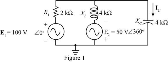
Fig. 19.142
Expert Solution & Answer
Want to see the full answer?
Check out a sample textbook solution
Students have asked these similar questions
Report:-
1. Plot (total core loss / cycle) as a function of frequency.
2. Evaluate (K & K2 )corresponding to value of (voltage & frequency).
3. Calculate hysteresis and eddy current losses at rated voltage and
frequency.
Not use ai please
Help on this equation system?
Chapter 19 Solutions
Laboratory Manual for Introductory Circuit Analysis
Ch. 19 - Using supeerposition, determine the current...Ch. 19 - Using superposition, determine the current through...Ch. 19 - Using superposition, determine the current IL for...Ch. 19 - Using superposition, determine the voltage across...Ch. 19 - Using superposition, determine the current through...Ch. 19 - Using superposition, find the sinusoidal...Ch. 19 - Using superposition, find the sinusoidal...Ch. 19 - Using superspostion, find the current I for the...Ch. 19 - Using superposition, determine the current IL...Ch. 19 - Using superposition, for the network of Fig....
Ch. 19 - Using superposition, determine the current IL for...Ch. 19 - Determine VL for the network of Fig. 19.116...Ch. 19 - Calculate the current I for the network of Fig....Ch. 19 - Find the voltage Vs for the network in Fig....Ch. 19 - Find the ThĂ©venin equivalent circuit for the...Ch. 19 - Find the Thevenin equivalent circuit for the...Ch. 19 - Find the Thevenin equivalent circuit for the...Ch. 19 - Find the Thevenin equivalent circuit for the...Ch. 19 - Find the Thevenin equivalent circuit for the...Ch. 19 - Find the Thevenin equivalent circuit for the...Ch. 19 - Find the ThĂªvenin equivalent circuit for the...Ch. 19 - Find the ThĂªvenin equivalent circuit for the...Ch. 19 - a. Find the ThĂ©venin equivalent circuit for the...Ch. 19 - a. Find the ThĂ©venin equivalent circuit for the...Ch. 19 - a. Find the ThĂ©venin equivalent circuit of the...Ch. 19 - Determine the ThĂ©venin equivalent circuit for the...Ch. 19 - Determine the ThĂ©venin equivalent circuit for the...Ch. 19 - Prob. 28PCh. 19 - Prob. 29PCh. 19 - Find the ThĂ©venin equivalent circuit for the...Ch. 19 - Determine the ThĂ©venin equivalent circuit for the...Ch. 19 - Prob. 32PCh. 19 - Find the ThĂ©venin equivalent circuit for the...Ch. 19 - Find the Norton equivalent circuit for the network...Ch. 19 - Find the Norton equivalent circuit for the network...Ch. 19 - Find the Norton equivalent circuit for the network...Ch. 19 - Find the Norton equivalent circuit for the portion...Ch. 19 - Find the Norton equivalent circuit for the portion...Ch. 19 - a. Find the Norton equivalent circuit for the...Ch. 19 - a. Find the Norton equivalent circuit for the...Ch. 19 - a. Find the Norton equivalent circuit for the...Ch. 19 - Determine the Norton equivalent circuit for the...Ch. 19 - Determine the Norton equivalent circuit for the...Ch. 19 - Find the Norton equivalent circuit for the network...Ch. 19 - Find the Norton equivalent circuit for the network...Ch. 19 - Prob. 46PCh. 19 - Prob. 47PCh. 19 - Find the load impedance ZL for the network of Fig....Ch. 19 - Find the load impedance ZL for the network of Fig....Ch. 19 - Find the load impedance ZL for the network of Fig....Ch. 19 - Find the load impedance ZL for the network of Fig....Ch. 19 - Prob. 52PCh. 19 - a. Determine the load impedance to replace the...Ch. 19 - a. Determine the load impedance to replace the...Ch. 19 - a. Determine the load impedance to replace the...Ch. 19 - Prob. 56PCh. 19 - a. For the network in Fig. 19.139, determine the...Ch. 19 - For the network in Fig. 19.140, determine two...Ch. 19 - Prob. 59PCh. 19 - Using Millmans theorem, determine the current...Ch. 19 - Prob. 61PCh. 19 - Determine the current IL for the network in Fig....Ch. 19 - Using schematics, determine V2 for the network in...Ch. 19 - Prob. 64PCh. 19 - Using schematics, plot the power to the R-C load...
Knowledge Booster


Learn more about
Need a deep-dive on the concept behind this application? Look no further. Learn more about this topic, electrical-engineering and related others by exploring similar questions and additional content below.Similar questions
- Transmitting and receiving antennas operating at 1 GHz with gains of 20 and 15 dB, respectively, are separated by a distance of 1 km. Find the power delivered to the load when the input power is 150 W. Assume the PLF = 1.arrow_forwardNot use ai pleasearrow_forwardNEED HANDWRITTEN SOLUTION DO NOT USE AI OR CHATGPTarrow_forward
- 2) Determine the voltage gain of the follower depicted in Fig. 2. Assume Is= 7 × 10-16. B = 100, VA = 5 V. Also assume the capacitors are very large. (40 points)arrow_forwardCalculate the voltage gain and I/O impedance of circuits shown in Fig. 1. Assume (60 points- each section 20 points) J Vina кат Vb J Vina кат VCC VCC VCC Vino - Vout - Vout Rs w Q2 Q2 (c) (b) Q2 = (a) - Voutarrow_forwardNot use ai please letarrow_forward
- Use PSpice to create the circuit and show the circuit along with simulation results. Also please explicitly answer the question (i.e. have the answer make sense and not in parts where there is no final answer.)arrow_forwardProblem 5 Plot the impulse response of the system shown below. Hint: This is done graphically with 4 convolutions. x[n] D y[n]< D D D D D D D D D D Darrow_forwardUse PSpice to create the circuit. Also please explicitly answer whether the load line intersects the -0.7 line at the computed point.arrow_forward
- In class, we wrote on the blackboard a byte addressable memory where each element was 2 nibbles: For example: Main memory A Address Offset Data Data Data Data Data Data Data Data Data Data Data Data Data Data Data Data 0 1 2 3 4 5 6 0 Ox10 0x00 0x02 0x2B Ox4F 0x00 0x00 0x00 0x11 0x12 0x20 0x10 0x10 0x00 OxFF Ox3E DxDD 0x00 0x00 0x00 0x00 0x00 0x00 0x00 7 0x1C 0x00 8 9 A 0x00 0x00 0x01 0x00 0x00 0x01 0x00 0x00 0x01 B с D E 0x00 0x05 0x04 0x03 0x02 0x00 Ox3D 0x00 0x1C Ox2F 0x00 Ox1F OxFF 0x03 0x02 F What is the contents of address 0x1C in main memory A for a 32 bit machine using Big Endian format? What is the contents of address 0x1C in main memory A for a 16 bit machine using Little Endian format? What is the contents of the indirect address at 0x04 in main memory A for a Big Endian 32 bit machine ((0x4))? What is the contents of 4(0x10) in main memory A for a 16 bit Little Endian machine? What is the contents of the address 16(0xC) for a 64 bit Little Endian machine?arrow_forwardProblem 4 Consider the system shown below where h₁[n] = {2,1,2} and h₂[n] = (n+1) u[n] (− means subtraction). h₂[n] x [n]- h₁[n] бел-27- h₂[n] y[n] (a) Determine the impulse response of the system and plot it for n = -3,...,6. (b) Determine graphically the response of the system to the following input. x[n] 2 4 5arrow_forwardNot use ai pleasearrow_forward
arrow_back_ios
SEE MORE QUESTIONS
arrow_forward_ios
Recommended textbooks for you

Inductors Explained - The basics how inductors work working principle; Author: The Engineering Mindset;https://www.youtube.com/watch?v=KSylo01n5FY;License: Standard Youtube License