
Laboratory Manual for Introductory Circuit Analysis
13th Edition
ISBN: 9780133923780
Author: Robert L. Boylestad, Gabriel Kousourou
Publisher: PEARSON
expand_more
expand_more
format_list_bulleted
Videos
Textbook Question
Chapter 19, Problem 19P
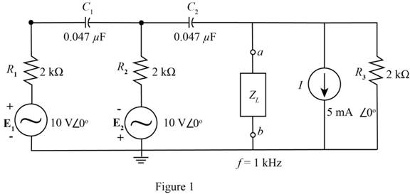
Find the Thevenin equivalent circuit for the portion of the network of Fig. 19.123 external to the load impedance ZL.
Expert Solution & Answer
Want to see the full answer?
Check out a sample textbook solution
Students have asked these similar questions
Solve by Pen and Paper not using chatgpt
f. The figure below shows two stage RC coupled amplifier. If the input resistance Rin
of each stage is 1kN. (B = 100). Determine its overall voltage gain. (5 marks)
+15V
ΣΚΩ
kn
10kΩ
10ΚΩ
output
35 ΚΩ
2ΚΩ
5kЛ
2ΚΩ
NO AI PLEASE
Chapter 19 Solutions
Laboratory Manual for Introductory Circuit Analysis
Ch. 19 - Using supeerposition, determine the current...Ch. 19 - Using superposition, determine the current through...Ch. 19 - Using superposition, determine the current IL for...Ch. 19 - Using superposition, determine the voltage across...Ch. 19 - Using superposition, determine the current through...Ch. 19 - Using superposition, find the sinusoidal...Ch. 19 - Using superposition, find the sinusoidal...Ch. 19 - Using superspostion, find the current I for the...Ch. 19 - Using superposition, determine the current IL...Ch. 19 - Using superposition, for the network of Fig....
Ch. 19 - Using superposition, determine the current IL for...Ch. 19 - Determine VL for the network of Fig. 19.116...Ch. 19 - Calculate the current I for the network of Fig....Ch. 19 - Find the voltage Vs for the network in Fig....Ch. 19 - Find the ThĂ©venin equivalent circuit for the...Ch. 19 - Find the Thevenin equivalent circuit for the...Ch. 19 - Find the Thevenin equivalent circuit for the...Ch. 19 - Find the Thevenin equivalent circuit for the...Ch. 19 - Find the Thevenin equivalent circuit for the...Ch. 19 - Find the Thevenin equivalent circuit for the...Ch. 19 - Find the ThĂªvenin equivalent circuit for the...Ch. 19 - Find the ThĂªvenin equivalent circuit for the...Ch. 19 - a. Find the ThĂ©venin equivalent circuit for the...Ch. 19 - a. Find the ThĂ©venin equivalent circuit for the...Ch. 19 - a. Find the ThĂ©venin equivalent circuit of the...Ch. 19 - Determine the ThĂ©venin equivalent circuit for the...Ch. 19 - Determine the ThĂ©venin equivalent circuit for the...Ch. 19 - Prob. 28PCh. 19 - Prob. 29PCh. 19 - Find the ThĂ©venin equivalent circuit for the...Ch. 19 - Determine the ThĂ©venin equivalent circuit for the...Ch. 19 - Prob. 32PCh. 19 - Find the ThĂ©venin equivalent circuit for the...Ch. 19 - Find the Norton equivalent circuit for the network...Ch. 19 - Find the Norton equivalent circuit for the network...Ch. 19 - Find the Norton equivalent circuit for the network...Ch. 19 - Find the Norton equivalent circuit for the portion...Ch. 19 - Find the Norton equivalent circuit for the portion...Ch. 19 - a. Find the Norton equivalent circuit for the...Ch. 19 - a. Find the Norton equivalent circuit for the...Ch. 19 - a. Find the Norton equivalent circuit for the...Ch. 19 - Determine the Norton equivalent circuit for the...Ch. 19 - Determine the Norton equivalent circuit for the...Ch. 19 - Find the Norton equivalent circuit for the network...Ch. 19 - Find the Norton equivalent circuit for the network...Ch. 19 - Prob. 46PCh. 19 - Prob. 47PCh. 19 - Find the load impedance ZL for the network of Fig....Ch. 19 - Find the load impedance ZL for the network of Fig....Ch. 19 - Find the load impedance ZL for the network of Fig....Ch. 19 - Find the load impedance ZL for the network of Fig....Ch. 19 - Prob. 52PCh. 19 - a. Determine the load impedance to replace the...Ch. 19 - a. Determine the load impedance to replace the...Ch. 19 - a. Determine the load impedance to replace the...Ch. 19 - Prob. 56PCh. 19 - a. For the network in Fig. 19.139, determine the...Ch. 19 - For the network in Fig. 19.140, determine two...Ch. 19 - Prob. 59PCh. 19 - Using Millmans theorem, determine the current...Ch. 19 - Prob. 61PCh. 19 - Determine the current IL for the network in Fig....Ch. 19 - Using schematics, determine V2 for the network in...Ch. 19 - Prob. 64PCh. 19 - Using schematics, plot the power to the R-C load...
Knowledge Booster


Learn more about
Need a deep-dive on the concept behind this application? Look no further. Learn more about this topic, electrical-engineering and related others by exploring similar questions and additional content below.Similar questions
- solve by impedancearrow_forwardConsider the circuit diagram below. Compute a single equivalent impedance for this circuit for a source frequency of F = 60 Hz. Express your final answer as a complex impedance with rectangular coordinates. You must show your all your work for the complex math. Include a diagram of the equivalent circuit as part of your solution.arrow_forwardConsider the circuit diagram below. Compute a single equivalent impedance for this circuit for a source frequency of f = 165 Hz. Express your final answer as a phasor with polar coordinates. You must show your all your work for the complex math. Include a diagram of the equivalent circuit as part of your solution.arrow_forward
- Consider the circuit diagram below. Using mesh analysis, compute the currents (a) IR1, (b) IL1, and (c) IC1. Express your final answers as phasors using polar coordinates with phase angles measured in degrees. Your solution should include the circuit diagram redrawn to indicate these currents and their directions. You must solve the system of equations using MATLAB and include the code or commands you ran as part of your solution.arrow_forwarduse kvl to solvearrow_forwardR1 is 978 ohms R2 is 2150 ohms R3 is 4780 R1 is parallel to R2 and R2 is parallel to R3 and R1 and R3 are in seriesarrow_forward
- Q7 For the circuit shown in Fig. 2.20, the transistors are identical and have the following parameters: hfe = 50, hie = 1.1K, hre = 0, and hoe = 0. Calculate Auf, Rif and Rof. Ans: 45.4; 112 KQ; 129. 25 V 10k 47k 4.7k Vo 150k w Vs 47k 4.7k W 22 5μF 33k 50uF 50μF 4.7k 4.7k R₁ Rof Rif R1000 Fig. 2.20 Circuit for Q7.arrow_forwardQ6)) The transistors in the feedback amplifier shown are identical, and their h-parameters are.. hie = 1.1k, hfe = 50, hre=o, and hoe = 0. Calculate Auf, Rif and Rof. {Ans: 6031583; 4. Kor. Is 4 4.7 k www 4.7k 91k 4.7k 91k 10k 1k. 10k 21000 4.7k w 15k Fig. 2.19 Circuit for Q6.arrow_forwardQ5 For the circuit shown in Fig. 2.18, hie =1.1 KQ, hfe =50. Find Avf, Rif and Rof Ans: -3.2; 193 ; 728 N. Vcc Vs Rs=10kQ Re=4KQ RF - = 40ΚΩ www Fig. 2.18 Circuit for Qs.arrow_forward
arrow_back_ios
SEE MORE QUESTIONS
arrow_forward_ios
Recommended textbooks for you
 Introductory Circuit Analysis (13th Edition)Electrical EngineeringISBN:9780133923605Author:Robert L. BoylestadPublisher:PEARSON
 Delmar's Standard Textbook Of ElectricityElectrical EngineeringISBN:9781337900348Author:Stephen L. HermanPublisher:Cengage Learning
 Programmable Logic ControllersElectrical EngineeringISBN:9780073373843Author:Frank D. PetruzellaPublisher:McGraw-Hill Education
 Fundamentals of Electric CircuitsElectrical EngineeringISBN:9780078028229Author:Charles K Alexander, Matthew SadikuPublisher:McGraw-Hill Education
 Electric Circuits. (11th Edition)Electrical EngineeringISBN:9780134746968Author:James W. Nilsson, Susan RiedelPublisher:PEARSON
 Engineering ElectromagneticsElectrical EngineeringISBN:9780078028151Author:Hayt, William H. (william Hart), Jr, BUCK, John A.Publisher:Mcgraw-hill Education,
Introductory Circuit Analysis (13th Edition)
Electrical Engineering
ISBN:9780133923605
Author:Robert L. Boylestad
Publisher:PEARSON
Delmar's Standard Textbook Of Electricity
Electrical Engineering
ISBN:9781337900348
Author:Stephen L. Herman
Publisher:Cengage Learning
Programmable Logic Controllers
Electrical Engineering
ISBN:9780073373843
Author:Frank D. Petruzella
Publisher:McGraw-Hill Education
Fundamentals of Electric Circuits
Electrical Engineering
ISBN:9780078028229
Author:Charles K Alexander, Matthew Sadiku
Publisher:McGraw-Hill Education
Electric Circuits. (11th Edition)
Electrical Engineering
ISBN:9780134746968
Author:James W. Nilsson, Susan Riedel
Publisher:PEARSON
Engineering Electromagnetics
Electrical Engineering
ISBN:9780078028151
Author:Hayt, William H. (william Hart), Jr, BUCK, John A.
Publisher:Mcgraw-hill Education,
Introduction to Two-Port Networks; Author: ALL ABOUT ELECTRONICS;https://www.youtube.com/watch?v=ru2ItcD6unI;License: Standard Youtube License