
Laboratory Manual for Introductory Circuit Analysis
13th Edition
ISBN: 9780133923780
Author: Robert L. Boylestad, Gabriel Kousourou
Publisher: PEARSON
expand_more
expand_more
format_list_bulleted
Videos
Textbook Question
Chapter 19, Problem 50P
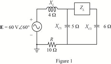
Find the load impedance ZL for the network of Fig. 19.135 for maximum power to the load, and find the maximum power to the load.
Expert Solution & Answer
Want to see the full answer?
Check out a sample textbook solution
Students have asked these similar questions
Enter the matrix values (numerical) to solve for voltages at nodes v1, and v2, for the circuit shown, using
Nodal equations. In the matrix, row 1, and row 2, correspond to node v1, and node v2 current
expressions, respectively. Let Is1=14, Is2=7, R₁=5, R₂-8, R3=2, and R4-5.
[G11 G12] [Vi₁
The matrix values are shown here:
=
G21 G22 [V2]
[41]
[12]
{Hint: As discussed in class and to avoid sign errors, assume nodal currents are locally defined at each
node (leaving) and use node labeling as indicated in the circuit. }
The relative tolerance for this problem is 5%.
VI
R2
ww
Isl
12
NODE v1
G11
G12
RI
1/Q
1/0
A
4=
NODE v2
G21-
1/Q
G22
1/0
12
W
A
===
www
R3
R4
www
Use Cramer's rule (matrix), substitution, or any other method to calculate the voltages:
v1 =
V
v2=
V
Is2
Only expert should attempt
For the circuit shown below, let l₁ = 9, 1₂ = 14, 13= 12, R₁ = 3, R₂ = 8, and R3 = 5.
Use nodal equations to determine V1, V2 and I, as follows:
• Consider Node 1, obtain a nodal equation in terms of V₁ and V₂ voltages. Simplify your equation
to the format
1V1 + b,V₂ = c, then enter the corresponding values of coefficients b₁ and c₁
1. b₁ =(
C₁ =
• Now consider Node 2, obtain a second nodal equation in terms of V₁ and V2 voltages. Simplify your
equation to the format
-1V₁+b2V2=c2 then enter the corresponding values of coefficients b₂ and c₂
2. (b₂ =
value.)
,၄၇ = -
3. Use (1) and (2) to determine V₂ =
4. Determine V₁
5. Determine | =
i
12
V₁
R1
20
www
R2
ww
I
The relative tolerance for this problem is 5%.
R3
This is not a decimal or integer
www
i3
Chapter 19 Solutions
Laboratory Manual for Introductory Circuit Analysis
Ch. 19 - Using supeerposition, determine the current...Ch. 19 - Using superposition, determine the current through...Ch. 19 - Using superposition, determine the current IL for...Ch. 19 - Using superposition, determine the voltage across...Ch. 19 - Using superposition, determine the current through...Ch. 19 - Using superposition, find the sinusoidal...Ch. 19 - Using superposition, find the sinusoidal...Ch. 19 - Using superspostion, find the current I for the...Ch. 19 - Using superposition, determine the current IL...Ch. 19 - Using superposition, for the network of Fig....
Ch. 19 - Using superposition, determine the current IL for...Ch. 19 - Determine VL for the network of Fig. 19.116...Ch. 19 - Calculate the current I for the network of Fig....Ch. 19 - Find the voltage Vs for the network in Fig....Ch. 19 - Find the ThĂ©venin equivalent circuit for the...Ch. 19 - Find the Thevenin equivalent circuit for the...Ch. 19 - Find the Thevenin equivalent circuit for the...Ch. 19 - Find the Thevenin equivalent circuit for the...Ch. 19 - Find the Thevenin equivalent circuit for the...Ch. 19 - Find the Thevenin equivalent circuit for the...Ch. 19 - Find the ThĂªvenin equivalent circuit for the...Ch. 19 - Find the ThĂªvenin equivalent circuit for the...Ch. 19 - a. Find the ThĂ©venin equivalent circuit for the...Ch. 19 - a. Find the ThĂ©venin equivalent circuit for the...Ch. 19 - a. Find the ThĂ©venin equivalent circuit of the...Ch. 19 - Determine the ThĂ©venin equivalent circuit for the...Ch. 19 - Determine the ThĂ©venin equivalent circuit for the...Ch. 19 - Prob. 28PCh. 19 - Prob. 29PCh. 19 - Find the ThĂ©venin equivalent circuit for the...Ch. 19 - Determine the ThĂ©venin equivalent circuit for the...Ch. 19 - Prob. 32PCh. 19 - Find the ThĂ©venin equivalent circuit for the...Ch. 19 - Find the Norton equivalent circuit for the network...Ch. 19 - Find the Norton equivalent circuit for the network...Ch. 19 - Find the Norton equivalent circuit for the network...Ch. 19 - Find the Norton equivalent circuit for the portion...Ch. 19 - Find the Norton equivalent circuit for the portion...Ch. 19 - a. Find the Norton equivalent circuit for the...Ch. 19 - a. Find the Norton equivalent circuit for the...Ch. 19 - a. Find the Norton equivalent circuit for the...Ch. 19 - Determine the Norton equivalent circuit for the...Ch. 19 - Determine the Norton equivalent circuit for the...Ch. 19 - Find the Norton equivalent circuit for the network...Ch. 19 - Find the Norton equivalent circuit for the network...Ch. 19 - Prob. 46PCh. 19 - Prob. 47PCh. 19 - Find the load impedance ZL for the network of Fig....Ch. 19 - Find the load impedance ZL for the network of Fig....Ch. 19 - Find the load impedance ZL for the network of Fig....Ch. 19 - Find the load impedance ZL for the network of Fig....Ch. 19 - Prob. 52PCh. 19 - a. Determine the load impedance to replace the...Ch. 19 - a. Determine the load impedance to replace the...Ch. 19 - a. Determine the load impedance to replace the...Ch. 19 - Prob. 56PCh. 19 - a. For the network in Fig. 19.139, determine the...Ch. 19 - For the network in Fig. 19.140, determine two...Ch. 19 - Prob. 59PCh. 19 - Using Millmans theorem, determine the current...Ch. 19 - Prob. 61PCh. 19 - Determine the current IL for the network in Fig....Ch. 19 - Using schematics, determine V2 for the network in...Ch. 19 - Prob. 64PCh. 19 - Using schematics, plot the power to the R-C load...
Knowledge Booster


Learn more about
Need a deep-dive on the concept behind this application? Look no further. Learn more about this topic, electrical-engineering and related others by exploring similar questions and additional content below.Similar questions
- For the circuit shown, let V1 = 19 V, Vs2 = 76 V, R₁ = 9, R2 = 9, and R3 = 7. Use Nodal analysis to determine the voltage V2 and the current lo, choose the closet values: V2- 4.788 10 = ○ 2.28 11.978 17.761 35.522 23.957 -9.146 8.32 10.173 A O-7.435 O-5.783 10.531 V sl ་ ་ ་ ན ་་་ ་ ་ ་ ་ ་ ་ ་ ་ +1 ww R₁ R₂ ww R3 Io +1 VS2arrow_forwardNO AI PLEASEarrow_forwardNO AI PLEASEarrow_forward
- Problem 4 Consider the following system. In the figure, y(t) denotes the displacement of the mass and u(t) denotes the force applied to the mass. b1 u(t) y(t) + b2 M 0000 0000 K1 K2 a) Find the differential equation model of the system. b) Find the state-space model for the system. Write x, A, B, C and D clearly in your answer.arrow_forwardNO AI PLEASEarrow_forwardNot use ai pleasearrow_forward
- Show workarrow_forwardProblem 1 (a) Suppose the Laplace transform of a causal signal x₁ (t) is given by S X₁(s) = 52 +2 Using the Laplace transform properties, find the Laplace transform of the following signal x2(t). x2(t) = e2t+1 x₁(t − 1) - tx₁(2t - 1) (b) Suppose an LTI system T whose impulse response is given by h(t) e 2t 1(t) t 1(t) +28(t) What is the transfer function of the system? (c) If the input x2 (t) is applied to the system T, what will be the output Y₂(s)? Note, you just need to provide Laplace transform of the output y₂(t). Simplification is not needed in any part of this question.arrow_forwardShow workarrow_forward
- B) A 60-Hz generator is supply ing 60% of P max to an infinite bus through a reactive network. A fault occurs which increases the reactance of the network between the generator internal voltage and the infinite bus by 400%. When the fault is cleared, the maximum power that can be delivered is 80% of the original maximum value. Determine the critical clearing angle for the condition described.arrow_forwardQ3) A: A generator operating at 50 Hz delivers 1 pu power to an infinite bus through a transmission circuit in which resistance is ignored. A fault takes place reducing the maximum powe transferable to 0.5 pu whereas before the fault, this power was 2.0 pu and after the clearance of the fault, it is 1.5 pu. By the use of equal area criterion, determine the critical clearing angle.arrow_forward4. For the periodic signal shown in Fig. 4; a) Find the exponential Fourier Series for y(t). b) Use Parseval's Theorem to compute the total power contained in the 4th harmonic and all higher harmonics. 2+ y(t) + -2л -л 0 2л Зл 4л Fig. 4arrow_forward
arrow_back_ios
SEE MORE QUESTIONS
arrow_forward_ios
Recommended textbooks for you
 Introductory Circuit Analysis (13th Edition)Electrical EngineeringISBN:9780133923605Author:Robert L. BoylestadPublisher:PEARSON
 Delmar's Standard Textbook Of ElectricityElectrical EngineeringISBN:9781337900348Author:Stephen L. HermanPublisher:Cengage Learning
 Programmable Logic ControllersElectrical EngineeringISBN:9780073373843Author:Frank D. PetruzellaPublisher:McGraw-Hill Education
 Fundamentals of Electric CircuitsElectrical EngineeringISBN:9780078028229Author:Charles K Alexander, Matthew SadikuPublisher:McGraw-Hill Education
 Electric Circuits. (11th Edition)Electrical EngineeringISBN:9780134746968Author:James W. Nilsson, Susan RiedelPublisher:PEARSON
 Engineering ElectromagneticsElectrical EngineeringISBN:9780078028151Author:Hayt, William H. (william Hart), Jr, BUCK, John A.Publisher:Mcgraw-hill Education,
Introductory Circuit Analysis (13th Edition)
Electrical Engineering
ISBN:9780133923605
Author:Robert L. Boylestad
Publisher:PEARSON
Delmar's Standard Textbook Of Electricity
Electrical Engineering
ISBN:9781337900348
Author:Stephen L. Herman
Publisher:Cengage Learning
Programmable Logic Controllers
Electrical Engineering
ISBN:9780073373843
Author:Frank D. Petruzella
Publisher:McGraw-Hill Education
Fundamentals of Electric Circuits
Electrical Engineering
ISBN:9780078028229
Author:Charles K Alexander, Matthew Sadiku
Publisher:McGraw-Hill Education
Electric Circuits. (11th Edition)
Electrical Engineering
ISBN:9780134746968
Author:James W. Nilsson, Susan Riedel
Publisher:PEARSON
Engineering Electromagnetics
Electrical Engineering
ISBN:9780078028151
Author:Hayt, William H. (william Hart), Jr, BUCK, John A.
Publisher:Mcgraw-hill Education,
Introduction to Two-Port Networks; Author: ALL ABOUT ELECTRONICS;https://www.youtube.com/watch?v=ru2ItcD6unI;License: Standard Youtube License