
Videos
After numerous experiments with a circuit configuration, you determined that as long as the transistor chosen meets certain criteria, other components in the circuit can be adjusted to yield an ideal frequency response. In the classification diagram shown, there are two regions where the transistor is acceptable.
Zone A, shown in solid magenta lines, is defined as:
- a horizontal line at 7500 Hz for voltages from 0 to 3 V;
- a linear line from (3, 7500) to (6, 9000);
- A vertical line at 6 V for a frequency from 6000 to 9000 Hz; and
- a power law curve which extends from (0, 0) to (6, 6000), passing through the point (3, 4244).
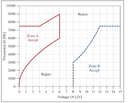
Zone B, shown n blue, dotted line segments, defined as
- a horizontal lire at 7500 Hz for voltages horn 12 to 15 V;
- a vertical line at 8 V for a frequency from 0 to 3000 Hz; and
- an exponential curve which extends from (8, 3000), to (12, 7500), passing through the point (11, 6000).
If a point fails on a line dividing the Accept and Reject regions, it is considered acceptable. Create the classification diagram, duplicating the diagram exactly as shown.
The user will be asked if they wish to enter a set of test values using a menu choice of Yes or No. If the user selects Yes, they will be allowed to specify a pair of experimental test values for a specific transistor and store the response in the two-element
As long as the user enters a two-element row vector and values are within the correct ranges, the program will follow these steps:
- The program will determine if the V. f pair entered by the user is Accepted or Rejected:
- If the test value lies in an Accept region, the program will save in the cell array the text Accept Device in Zone # in a variable where # is replaced by the letter A or B depending on the Zone the point lies in.
- If the test value in anywhere outside an Accept region, the program will save in the cell array the test Reject Device.
- The program should also keep track, as running totals, of the number of points that have been accepted and the number rejected.
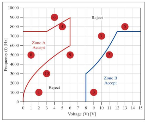
- The point is added to the classification diagram as a size 20 red, solid circle. The center of the circle should contain the point number entered by the user (1 for first point, 2 for second point, etc.)
- The user is then prompted by the menu to select if they wish to enter another pair of test values.
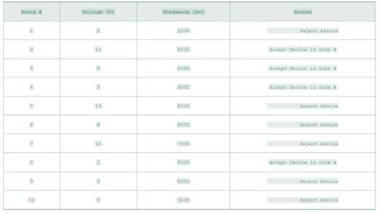
- If the user selects No from the menu or closes the menu at any time the program will end the input loop and show the results in the Command Window. If the user has entered at least one valid rosy vector and then enters a voltage value outside the acceptable range of 0 to 15 volts, the program will print the results in tabular format, similar to the following table. It will also report the number of points accepted and number of points rejected that were entered by the user.
Example showing tabular output to Command Window and the graph created
Your teats resulted in:
4Accepted Devices
6 Rejected Devices
Want to see the full answer?
Check out a sample textbook solution
Chapter 19 Solutions
THINKING LIKE AN ENGINEER W/ACCESS


- A ship 140 m long and 18 m beam floats at a draught of9 m. The immersed cross-sectionai areas at equai intervais are 5,60, 116, 145, 152, 153, 153, 151, 142, 85 and 0 m2 respectively.Calculate:(a) displacement(b) block coefficient(c) midship section area coefficient(d) prismatic coefficient.arrow_forwardA steamer has waterplane area 1680m2 recorded in water with relative denisty 1.013. Displacement = 1200 t, calculate difference in draught in salwater reltive denisity 1.025.arrow_forwardrelative velocity 11.72 m/s is correct, need help finding the angle pleasearrow_forward
- Determine the distance between the two automobiles 2 s after A has passed through the intersection.arrow_forwardA box barge 65 m long and 12 m wide floats at a draught of5.5 m in sea water. Calculate:(a) the displacement of the barge,(b) its draught in fresh waterarrow_forwardwhat is the angle of the velocity of block B? velocity is 7.46 in/s Determine the acceleration and angle of block B. (Round the acceleration value to three decimal places.)arrow_forward
- Determine the relative velocity of B with respect to A.arrow_forwardGenerate the kinematic diagram of the following mechanism. Then, draw their graphs and calculate their degrees of freedom (DoF) using Gruebler's formula.arrow_forwardAn elastic bar of length L = 1m and cross section A = 1cm2 spins with angular velocity ω about an axis, as shown in the figure below. The radial acceleration at a generic point x along the bar is a(x) = ω2x, where ω= 100rad/s is the angular velocity. The bar is pinned on the rotation axis at x = 0. A mass M = 1kg is attached to the right end of the bar. Due to the radial acceleration, the bar stretches along x with displacement function u(x). The displacement u(x) solves the BVP (strong form) sketched below: d dx (σ(x)) + ρa(x) = 0 PDE σ(x) = E du dx Hooke’s law (1) u(0) =?? essential BC σ(L) =?? natural BC where σ(x) is the axial stress in the rod, ρ= 2700kg /m3 is the mass density, and E = 70GPa is the Young’s modulus 1. Define appropriate BCs for the strong BVP 2. Find the solution of the strong BVP analytically 3. Derive the weak form of the BVP.arrow_forward
- Gruebler's formula for the following mechanism?arrow_forwardw/I - | العنوان I need a detailed drawing with explanation SOLL эт 4 حكا The guide vane angle of a reaction turbine (Francis type make 20° with the tangent. The moving blade angle at entry is 120°. The external diameter of runner is 450 mm and the internal diameter is 300 mm. Runner width at entry is 62.5mm and at exit 100mm. Calculate the blade angle at exit for radial discharge. 96252 -20125 750 ×2.01arrow_forwardCompressor Selection: (Q1) While a manufacturing cell is running, the calculated flow rate of air into a compressor is 40 SCFM. Which compressor from this list should be selected? A. A compressor that uses 80 SCFM B. A compressor that uses 40 SCFM C. A compressor that delivers 80 SCFM D. A compressor that delivers 40 SCFMarrow_forward
 Elements Of ElectromagneticsMechanical EngineeringISBN:9780190698614Author:Sadiku, Matthew N. O.Publisher:Oxford University Press
 Mechanics of Materials (10th Edition)Mechanical EngineeringISBN:9780134319650Author:Russell C. HibbelerPublisher:PEARSON
 Thermodynamics: An Engineering ApproachMechanical EngineeringISBN:9781259822674Author:Yunus A. Cengel Dr., Michael A. BolesPublisher:McGraw-Hill Education
 Control Systems EngineeringMechanical EngineeringISBN:9781118170519Author:Norman S. NisePublisher:WILEY
 Mechanics of Materials (MindTap Course List)Mechanical EngineeringISBN:9781337093347Author:Barry J. Goodno, James M. GerePublisher:Cengage Learning
 Engineering Mechanics: StaticsMechanical EngineeringISBN:9781118807330Author:James L. Meriam, L. G. Kraige, J. N. BoltonPublisher:WILEY