Engineering Mechanics: Dynamics (14th Edition)
14th Edition
ISBN: 9780133915389
Author: Russell C. Hibbeler
Publisher: PEARSON
expand_more
expand_more
format_list_bulleted
Videos
Textbook Question
Chapter 18.5, Problem 49P
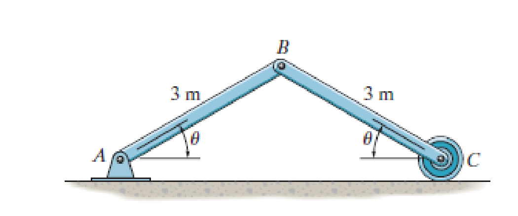
If the bars are released from rest when θ = 60°, determine their angular velocities at the instant θ = 30°. The 5-kg disk at C has a radius of 0.5 m and rolls without slipping.
Expert Solution & Answer
Want to see the full answer?
Check out a sample textbook solution
Students have asked these similar questions
The resistance R and load effect S for a given failure mode are statistically independent random variables
with marginal PDF's
1
fR (r) =
0≤r≤100
100'
fs(s)=0.05e-0.05s
(a) Determine the probability of failure by computing the probability content of the failure domain defined
as {r
Please solve this problem as soon as possible My ID# 016948724
The gears shown in the figure have a diametral pitch of 2 teeth per inch and a 20° pressure angle.
The pinion rotates at 1800 rev/min clockwise and transmits 200 hp through the idler pair to gear
5 on shaft c. What forces do gears 3 and 4 transmit to the idler shaft?
TS
I
y
18T
32T
This
a
12
x
18T
C
48T
5
Chapter 18 Solutions
Engineering Mechanics: Dynamics (14th Edition)
Ch. 18.4 - Determine the kinetic energy of the 100-kg object.Ch. 18.4 - The 80-kg wheel has a radius of gyration about its...Ch. 18.4 - If the rod is at rest when = 0, determine its...Ch. 18.4 - Determine the angular velocity of the rod when the...Ch. 18.4 - If the wheel starts from rest and rolls Without...Ch. 18.4 - If the uniform 30-kg slender rod starts from rest...Ch. 18.4 - When it is subjected to a couple moment of M = 50...Ch. 18.4 - Show that its kinetic energy can be represented a...Ch. 18.4 - If the torsional spring attached to the wheel's...Ch. 18.4 - If the torsional spring attached to the wheel's...
Ch. 18.4 - Determine the angular velocity of the reel after...Ch. 18.4 - Determine the angular velocity of the reel after...Ch. 18.4 - Determine the angular velocity of the reel after...Ch. 18.4 - It has a weight of 50 lb and a centroidal radius...Ch. 18.4 - It has a weight of 50 lb and a centro1dal radius...Ch. 18.4 - If it starts from rest, determine its angular...Ch. 18.4 - If the 10-kg block is released from rest,...Ch. 18.4 - Determine the angular velocity of the 20-kg wheel...Ch. 18.4 - Initially, the system is at rest. The reel has a...Ch. 18.4 - The force is always perpendicular to the rod.Ch. 18.4 - Determine the angular velocity of the rod when it...Ch. 18.4 - If it is released from rest in the position shown,...Ch. 18.4 - If the elevator has a mass of 900 kg, the...Ch. 18.4 - If the ring rolls without slipping, determine its...Ch. 18.4 - A motor supplies a torque M = (40 + 900) Nm ,...Ch. 18.4 - When empty it has a mass of 800 kg and a radius of...Ch. 18.4 - If P = 200 N and the 15-kg uniform slender rod...Ch. 18.4 - If it is released from rest, determine how far it...Ch. 18.4 - The windlass A can be considered as a 30-lb...Ch. 18.4 - If the conveyor belt is moving with a speed of Vc...Ch. 18.4 - A couple moment of M = 80 Nm is then applied to...Ch. 18.4 - A couple moment M = 80 Nm is then applied to the...Ch. 18.4 - If the plate is released from rest at = 90,...Ch. 18.4 - If the ring gear C is fixed, determine the angular...Ch. 18.4 - If the rod is released from rest when the spring...Ch. 18.4 - Determine the speed of the sptere's center of mass...Ch. 18.4 - Motor M exerts a constant force of P = 750 Non the...Ch. 18.4 - When = 0, rod AB is rotating with an angular...Ch. 18.4 - If rod CD is subjected to a couple moment M = 30...Ch. 18.4 - The gears roll within the fixed ring gear C, which...Ch. 18.4 - When = 0, rod AB is rotating with an angular...Ch. 18.4 - When = 0, rod AB is rotating with an angular...Ch. 18.5 - If the 30-kg disk is released from rest when = 0...Ch. 18.5 - If it is released from rest, determine its angular...Ch. 18.5 - Determine its angular velocity when = 45.The...Ch. 18.5 - Determine the angular velocity of the rod when =...Ch. 18.5 - Determine the angular velocity of the rod when =...Ch. 18.5 - Determine its angular velocity when = 90. The...Ch. 18.5 - If a 2-kg block is suspended from the cord,...Ch. 18.5 - Prob. 37PCh. 18.5 - If it is released from rest at A on the incline,...Ch. 18.5 - The spool has a mass of 20 kg and a radius of...Ch. 18.5 - If the 15-kg block A is released from rest,...Ch. 18.5 - If it is allowed to fall freely determine the...Ch. 18.5 - Gear A has a mass of 10kg and a radius of gyration...Ch. 18.5 - If the rod is released from rest when = 30,...Ch. 18.5 - If the rod is released from rest when = 30,...Ch. 18.5 - The 40-kg wheel has a radius of gyration about its...Ch. 18.5 - If the bars are released from rest when = 60,...Ch. 18.5 - If the bars are released from rest when = 60,...Ch. 18.5 - If it has a mass of 3 kg and a rad1us of gyration...Ch. 18.5 - Lifting is done using the two springs, each of...Ch. 18.5 - If the spring has an unstretched length of 1.5 m,...Ch. 18.5 - If the spring has an unstretched length of 1.5 m,...Ch. 18.5 - The drum has a weight of 50 lb and a radius of...Ch. 18.5 - If the track in which it moves is smooth,...Ch. 18.5 - The pulley has a weight of 50 lb and a rad1us of...Ch. 18.5 - The gear has a weight of 100 lb and a radius of...Ch. 18.5 - Determine the stiffness k of the spring so that...Ch. 18.5 - The slender 6-kg bar AB is horizontal and at rest...Ch. 18.5 - If the spring has an unstretched length of 0.2 m,...Ch. 18.5 - The 500-g rod AB rests along the smooth inner...Ch. 18.5 - The 50-lb wheel has a radius of gyration about its...Ch. 18.5 - The system consists of 60-lb and 20-lb blocks A...Ch. 18.5 - The door is made from one piece, whose ends move...Ch. 18.5 - The door is made from one piece, whose ends move...Ch. 18.5 - The end A of the garage door AB travels along the...Ch. 18.5 - The system consists of a 30-kg disk, 12-kg slender...Ch. 18.5 - The system consists of a 30-kg disk A, 12-kg...Ch. 18.5 - If it is released from rest when = 0, determine...Ch. 18.5 - If it is subjected to a torque of M = (91/2+ 1)...Ch. 18.5 - Starting from rest, the suspended 15-kg block B is...Ch. 18.5 - If it is released from rest, determine how far its...Ch. 18.5 - If the rack is originally moving downward at 2...Ch. 18.5 - The spring attached to its end always remains...Ch. 18.5 - If the disk rolls without slipping, determine the...Ch. 18.5 - At the instant the spring becomes undeformed, the...
Knowledge Booster


Learn more about
Need a deep-dive on the concept behind this application? Look no further. Learn more about this topic, mechanical-engineering and related others by exploring similar questions and additional content below.Similar questions
- Question 1. Draw 3 teeth for the following pinion and gear respectively. The teeth should be drawn near the pressure line so that the teeth from the pinion should mesh those of the gear. Drawing scale (1:1). Either a precise hand drawing or CAD drawing is acceptable. Draw all the trajectories of the involute lines and the circles. Specification: 18tooth pinion and 30tooth gear. Diameter pitch=P=6 teeth /inch. Pressure angle:20°, 1/P for addendum (a) and 1.25/P for dedendum (b). For fillet, c=b-a.arrow_forward5. The figure shows a gear train. There is no friction at the bearings except for the gear tooth forces. The material of the milled gears is steel having a Brinell hardness of 170. The input shaft speed (n2) is 800 rpm. The face width and the contact angle for all gears are 1 in and 20° respectively. In this gear set, the endurance limit (Se) is 15 kpsi and nd (design factor) is 2. (a) Find the revolution speed of gear 5. (b) Determine whether each gear satisfies the design factor of 2.0 for bending fatigue. (c) Determine whether each gear satisfies the design factor of 2.0 for surface fatigue (contact stress). (d) According to the computation results of the questions (b) and (c), explain the possible failure mechanisms for each gear. N4=28 800rpm N₁=43 N5=34 N₂=14 P(diameteral pitch)=8 for all gears Coupled to 2.5hp motorarrow_forward1. The rotating steel shaft is simply supported by bearings at points of B and C, and is driven by a spur gear at D, which has a 6-in pitch diameter. The force F from the drive gear acts at a pressure angle of 20°. The shaft transmits a torque to point A of TA =3000 lbĘ in. The shaft is machined from steel with Sy=60kpsi and Sut=80 kpsi. (1) Draw a shear force diagram and a bending moment diagram by F. According to your analysis, where is the point of interest to evaluate the safety factor among A, B, C, and D? Describe the reason. (Hint: To find F, the torque Tд is generated by the tangential force of F (i.e. Ftangential-Fcos20°) When n=2.5, K=1.8, and K₁ =1.3, determine the diameter of the shaft based on (2) static analysis using DE theory (note that fatigue stress concentration factors need to be used for this question because the loading condition is fatigue) and (3) a fatigue analysis using modified Goodman. Note) A standard diameter is not required for the questions. 10 in Darrow_forward
- 3 N2=28 P(diametral pitch)=8 for all gears Coupled to 25 hp motor N3=34 Full depth spur gears with pressure angle=20° N₂=2000 rpm (1) Compute the circular pitch, the center-to-center distance, and base circle radii. (2) Draw the free body diagram of gear 3 and show all the forces and the torque. (3) In mounting gears, the center-to-center distance was reduced by 0.1 inch. Calculate the new values of center-to-center distance, pressure angle, base circle radii, and pitch circle diameters. (4)What is the new tangential and radial forces for gear 3? (5) Under the new center to center distance, is the contact ratio (mc) increasing or decreasing?arrow_forward2. A flat belt drive consists of two 4-ft diameter cast-iron pulleys spaced 16 ft apart. A power of 60 hp is transmitted by a pulley whose speed is 380 rev/min. Use a service factor (Ks) pf 1.1 and a design factor 1.0. The width of the polyamide A-3 belt is 6 in. Use CD=1. Answer the following questions. (1) What is the total length of the belt according to the given geometry? (2) Find the centrifugal force (Fc) applied to the belt. (3) What is the transmitted torque through the pulley system given 60hp? (4) Using the allowable tension, find the force (F₁) on the tight side. What is the tension at the loose side (F2) and the initial tension (F.)? (5) Using the forces, estimate the developed friction coefficient (f) (6) Based on the forces and the given rotational speed, rate the pulley set. In other words, what is the horse power that can be transmitted by the pulley system? (7) To reduce the applied tension on the tight side, the friction coefficient is increased to 0.75. Find out the…arrow_forwardThe tooth numbers for the gear train illustrated are N₂ = 24, N3 = 18, №4 = 30, №6 = 36, and N₁ = 54. Gear 7 is fixed. If shaft b is turned through 5 revolutions, how many turns will shaft a make? a 5 [6] barrow_forward
- Please do not use any AI tools to solve this question. I need a fully manual, step-by-step solution with clear explanations, as if it were done by a human tutor. No AI-generated responses, please.arrow_forwardPlease do not use any AI tools to solve this question. I need a fully manual, step-by-step solution with clear explanations, as if it were done by a human tutor. No AI-generated responses, please.arrow_forwardCE-112 please solve this problem step by step and give me the correct answerarrow_forward
arrow_back_ios
SEE MORE QUESTIONS
arrow_forward_ios
Recommended textbooks for you
 International Edition---engineering Mechanics: St...Mechanical EngineeringISBN:9781305501607Author:Andrew Pytel And Jaan KiusalaasPublisher:CENGAGE L
 Automotive Technology: A Systems Approach (MindTa...Mechanical EngineeringISBN:9781133612315Author:Jack Erjavec, Rob ThompsonPublisher:Cengage Learning
International Edition---engineering Mechanics: St...
Mechanical Engineering
ISBN:9781305501607
Author:Andrew Pytel And Jaan Kiusalaas
Publisher:CENGAGE L
Automotive Technology: A Systems Approach (MindTa...
Mechanical Engineering
ISBN:9781133612315
Author:Jack Erjavec, Rob Thompson
Publisher:Cengage Learning
Mechanical SPRING DESIGN Strategy and Restrictions in Under 15 Minutes!; Author: Less Boring Lectures;https://www.youtube.com/watch?v=dsWQrzfQt3s;License: Standard Youtube License