Engineering Mechanics: Dynamics (14th Edition)
14th Edition
ISBN: 9780133915389
Author: Russell C. Hibbeler
Publisher: PEARSON
expand_more
expand_more
format_list_bulleted
Concept explainers
Videos
Textbook Question
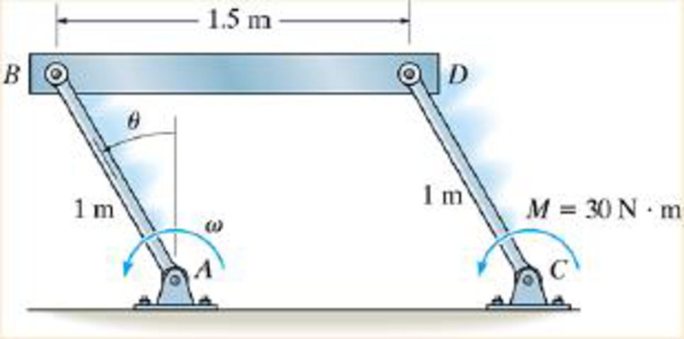
Chapter 18.4, Problem 32P
If rod CD is subjected to a couple moment M = 30 N·m, determine ω at the instant θ = 45°
Expert Solution & Answer
Want to see the full answer?
Check out a sample textbook solution
Students have asked these similar questions
PROBLEM 3.23
3.23 Under normal operating condi-
tions a motor exerts a torque of
magnitude TF at F. The shafts
are made of a steel for which
the allowable shearing stress is
82 MPa and have diameters of
dCDE=24 mm and dFGH = 20
mm. Knowing that rp = 165
mm and rg114 mm, deter-
mine the largest torque TF
which may be exerted at F.
TF
F
rG-
rp
B
CH
TE
E
1. (16%) (a) If a ductile material fails under pure torsion, please explain the failure
mode and describe the observed plane of failure.
(b) Suppose a prismatic beam is subjected to equal and opposite couples as shown
in Fig. 1. Please sketch the deformation and the stress distribution of the cross
section.
M
M
Fig. 1
(c) Describe the definition of the neutral axis.
(d) Describe the definition of the modular ratio.
using the theorem of three moments, find all the moments, I only need concise calculations with minimal explanations. The correct answers are provided at the bottom
Chapter 18 Solutions
Engineering Mechanics: Dynamics (14th Edition)
Ch. 18.4 - Determine the kinetic energy of the 100-kg object.Ch. 18.4 - The 80-kg wheel has a radius of gyration about its...Ch. 18.4 - If the rod is at rest when = 0, determine its...Ch. 18.4 - Determine the angular velocity of the rod when the...Ch. 18.4 - If the wheel starts from rest and rolls Without...Ch. 18.4 - If the uniform 30-kg slender rod starts from rest...Ch. 18.4 - When it is subjected to a couple moment of M = 50...Ch. 18.4 - Show that its kinetic energy can be represented a...Ch. 18.4 - If the torsional spring attached to the wheel's...Ch. 18.4 - If the torsional spring attached to the wheel's...
Ch. 18.4 - Determine the angular velocity of the reel after...Ch. 18.4 - Determine the angular velocity of the reel after...Ch. 18.4 - Determine the angular velocity of the reel after...Ch. 18.4 - It has a weight of 50 lb and a centroidal radius...Ch. 18.4 - It has a weight of 50 lb and a centro1dal radius...Ch. 18.4 - If it starts from rest, determine its angular...Ch. 18.4 - If the 10-kg block is released from rest,...Ch. 18.4 - Determine the angular velocity of the 20-kg wheel...Ch. 18.4 - Initially, the system is at rest. The reel has a...Ch. 18.4 - The force is always perpendicular to the rod.Ch. 18.4 - Determine the angular velocity of the rod when it...Ch. 18.4 - If it is released from rest in the position shown,...Ch. 18.4 - If the elevator has a mass of 900 kg, the...Ch. 18.4 - If the ring rolls without slipping, determine its...Ch. 18.4 - A motor supplies a torque M = (40 + 900) Nm ,...Ch. 18.4 - When empty it has a mass of 800 kg and a radius of...Ch. 18.4 - If P = 200 N and the 15-kg uniform slender rod...Ch. 18.4 - If it is released from rest, determine how far it...Ch. 18.4 - The windlass A can be considered as a 30-lb...Ch. 18.4 - If the conveyor belt is moving with a speed of Vc...Ch. 18.4 - A couple moment of M = 80 Nm is then applied to...Ch. 18.4 - A couple moment M = 80 Nm is then applied to the...Ch. 18.4 - If the plate is released from rest at = 90,...Ch. 18.4 - If the ring gear C is fixed, determine the angular...Ch. 18.4 - If the rod is released from rest when the spring...Ch. 18.4 - Determine the speed of the sptere's center of mass...Ch. 18.4 - Motor M exerts a constant force of P = 750 Non the...Ch. 18.4 - When = 0, rod AB is rotating with an angular...Ch. 18.4 - If rod CD is subjected to a couple moment M = 30...Ch. 18.4 - The gears roll within the fixed ring gear C, which...Ch. 18.4 - When = 0, rod AB is rotating with an angular...Ch. 18.4 - When = 0, rod AB is rotating with an angular...Ch. 18.5 - If the 30-kg disk is released from rest when = 0...Ch. 18.5 - If it is released from rest, determine its angular...Ch. 18.5 - Determine its angular velocity when = 45.The...Ch. 18.5 - Determine the angular velocity of the rod when =...Ch. 18.5 - Determine the angular velocity of the rod when =...Ch. 18.5 - Determine its angular velocity when = 90. The...Ch. 18.5 - If a 2-kg block is suspended from the cord,...Ch. 18.5 - Prob. 37PCh. 18.5 - If it is released from rest at A on the incline,...Ch. 18.5 - The spool has a mass of 20 kg and a radius of...Ch. 18.5 - If the 15-kg block A is released from rest,...Ch. 18.5 - If it is allowed to fall freely determine the...Ch. 18.5 - Gear A has a mass of 10kg and a radius of gyration...Ch. 18.5 - If the rod is released from rest when = 30,...Ch. 18.5 - If the rod is released from rest when = 30,...Ch. 18.5 - The 40-kg wheel has a radius of gyration about its...Ch. 18.5 - If the bars are released from rest when = 60,...Ch. 18.5 - If the bars are released from rest when = 60,...Ch. 18.5 - If it has a mass of 3 kg and a rad1us of gyration...Ch. 18.5 - Lifting is done using the two springs, each of...Ch. 18.5 - If the spring has an unstretched length of 1.5 m,...Ch. 18.5 - If the spring has an unstretched length of 1.5 m,...Ch. 18.5 - The drum has a weight of 50 lb and a radius of...Ch. 18.5 - If the track in which it moves is smooth,...Ch. 18.5 - The pulley has a weight of 50 lb and a rad1us of...Ch. 18.5 - The gear has a weight of 100 lb and a radius of...Ch. 18.5 - Determine the stiffness k of the spring so that...Ch. 18.5 - The slender 6-kg bar AB is horizontal and at rest...Ch. 18.5 - If the spring has an unstretched length of 0.2 m,...Ch. 18.5 - The 500-g rod AB rests along the smooth inner...Ch. 18.5 - The 50-lb wheel has a radius of gyration about its...Ch. 18.5 - The system consists of 60-lb and 20-lb blocks A...Ch. 18.5 - The door is made from one piece, whose ends move...Ch. 18.5 - The door is made from one piece, whose ends move...Ch. 18.5 - The end A of the garage door AB travels along the...Ch. 18.5 - The system consists of a 30-kg disk, 12-kg slender...Ch. 18.5 - The system consists of a 30-kg disk A, 12-kg...Ch. 18.5 - If it is released from rest when = 0, determine...Ch. 18.5 - If it is subjected to a torque of M = (91/2+ 1)...Ch. 18.5 - Starting from rest, the suspended 15-kg block B is...Ch. 18.5 - If it is released from rest, determine how far its...Ch. 18.5 - If the rack is originally moving downward at 2...Ch. 18.5 - The spring attached to its end always remains...Ch. 18.5 - If the disk rolls without slipping, determine the...Ch. 18.5 - At the instant the spring becomes undeformed, the...
Knowledge Booster


Learn more about
Need a deep-dive on the concept behind this application? Look no further. Learn more about this topic, mechanical-engineering and related others by exploring similar questions and additional content below.Similar questions
- PROBLEM 3.46 The solid cylindrical rod BC of length L = 600 mm is attached to the rigid lever AB of length a = 380 mm and to the support at C. When a 500 N force P is applied at A, design specifications require that the displacement of A not exceed 25 mm when a 500 N force P is applied at A For the material indicated determine the required diameter of the rod. Aluminium: Tall = 65 MPa, G = 27 GPa. Aarrow_forwardFind the equivalent mass of the rocker arm assembly with respect to the x coordinate. k₁ mi m2 k₁arrow_forward2. Figure below shows a U-tube manometer open at both ends and containing a column of liquid mercury of length l and specific weight y. Considering a small displacement x of the manometer meniscus from its equilibrium position (or datum), determine the equivalent spring constant associated with the restoring force. Datum Area, Aarrow_forward
- 1. The consequences of a head-on collision of two automobiles can be studied by considering the impact of the automobile on a barrier, as shown in figure below. Construct a mathematical model (i.e., draw the diagram) by considering the masses of the automobile body, engine, transmission, and suspension and the elasticity of the bumpers, radiator, sheet metal body, driveline, and engine mounts.arrow_forward3.) 15.40 – Collar B moves up at constant velocity vB = 1.5 m/s. Rod AB has length = 1.2 m. The incline is at angle = 25°. Compute an expression for the angular velocity of rod AB, ė and the velocity of end A of the rod (✓✓) as a function of v₂,1,0,0. Then compute numerical answers for ȧ & y_ with 0 = 50°.arrow_forward2.) 15.12 The assembly shown consists of the straight rod ABC which passes through and is welded to the grectangular plate DEFH. The assembly rotates about the axis AC with a constant angular velocity of 9 rad/s. Knowing that the motion when viewed from C is counterclockwise, determine the velocity and acceleration of corner F.arrow_forward
arrow_back_ios
SEE MORE QUESTIONS
arrow_forward_ios
Recommended textbooks for you
 Elements Of ElectromagneticsMechanical EngineeringISBN:9780190698614Author:Sadiku, Matthew N. O.Publisher:Oxford University Press
 Mechanics of Materials (10th Edition)Mechanical EngineeringISBN:9780134319650Author:Russell C. HibbelerPublisher:PEARSON
 Thermodynamics: An Engineering ApproachMechanical EngineeringISBN:9781259822674Author:Yunus A. Cengel Dr., Michael A. BolesPublisher:McGraw-Hill Education
 Control Systems EngineeringMechanical EngineeringISBN:9781118170519Author:Norman S. NisePublisher:WILEY
 Mechanics of Materials (MindTap Course List)Mechanical EngineeringISBN:9781337093347Author:Barry J. Goodno, James M. GerePublisher:Cengage Learning
 Engineering Mechanics: StaticsMechanical EngineeringISBN:9781118807330Author:James L. Meriam, L. G. Kraige, J. N. BoltonPublisher:WILEY
Elements Of Electromagnetics
Mechanical Engineering
ISBN:9780190698614
Author:Sadiku, Matthew N. O.
Publisher:Oxford University Press
Mechanics of Materials (10th Edition)
Mechanical Engineering
ISBN:9780134319650
Author:Russell C. Hibbeler
Publisher:PEARSON
Thermodynamics: An Engineering Approach
Mechanical Engineering
ISBN:9781259822674
Author:Yunus A. Cengel Dr., Michael A. Boles
Publisher:McGraw-Hill Education
Control Systems Engineering
Mechanical Engineering
ISBN:9781118170519
Author:Norman S. Nise
Publisher:WILEY
Mechanics of Materials (MindTap Course List)
Mechanical Engineering
ISBN:9781337093347
Author:Barry J. Goodno, James M. Gere
Publisher:Cengage Learning
Engineering Mechanics: Statics
Mechanical Engineering
ISBN:9781118807330
Author:James L. Meriam, L. G. Kraige, J. N. Bolton
Publisher:WILEY
Everything About COMBINED LOADING in 10 Minutes! Mechanics of Materials; Author: Less Boring Lectures;https://www.youtube.com/watch?v=N-PlI900hSg;License: Standard youtube license