Concept explainers
Videos
Determine the kinetic energy of the 100-kg object.
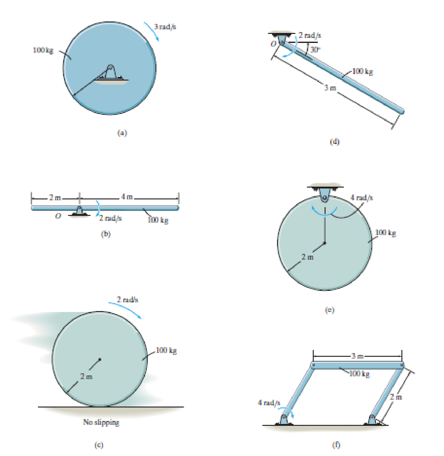
a)
The kinetic energy of the object:
Answer to Problem 1PP
The kinetic energy of the disk is
Explanation of Solution
Given:
The mass of disk is
The angular velocity of the disk is
The radius of the disk is
Draw the free body diagram of the rod as shown in Figure (1a).
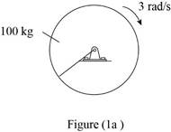
Refer Figure (1a).
Write the formula for mass moment of inertia
Here,
Write the formula for kinetic energy
(Rotation about fixed axis).
Substitute
Here,
Conclusion:
Calculate the kinetic energy of the disk.
Substitute
Thus, the kinetic energy of the disk is
b)
The kinetic energy of the object:
Answer to Problem 1PP
The kinetic energy of the disk is
Explanation of Solution
Given:
The mass of rod is
The angular velocity of the rod is
The length of the rod is
Draw the free body diagram of the rod as shown in Figure (1b).
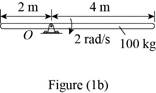
Refer Figure (1b).
Write the formula for mass moment of inertia
Here,
Substitute
Here,
Write the formula for kinetic energy
Substitute
Here,
Conclusion:
Refer Figure (1b).
Calculate the kinetic energy of the rod.
Substitute
Thus, the kinetic energy of the rod is
c)
The kinetic energy of the object:
Answer to Problem 1PP
The kinetic energy of the disk is
Explanation of Solution
Given:
The mass of disk is
The angular velocity of the disk is
The radius of the disk is
Draw the free body diagram of the disk as shown in Figure (1c).
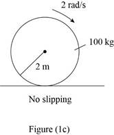
Refer Figure (1c).
Write the formula for mass moment of inertia
Here,
Write the formula for kinetic energy
Here,
Substitute
Here,
Conclusion:
Refer Figure (1c).
Calculate the kinetic energy of the disk.
Substitute
Thus, the kinetic energy of the disk is
d)
The kinetic energy of the object:
Answer to Problem 1PP
The kinetic energy of the rod is
Explanation of Solution
Given:
The mass of rod is
The angular velocity of the rod is
The length of the rod is
Draw the free body diagram of the rod as shown in Figure (1d).
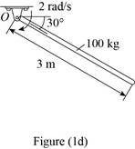
Refer Figure (1d).
Write the formula for mass moment of inertia
Here,
Write the formula for kinetic energy
(Rotation about fixed axis).
Substitute
Here,
Conclusion:
Refer Figure (1d).
Calculate the kinetic energy of the rod.
Substitute
Thus, the kinetic energy of the rod is
e)
The kinetic energy of the object:
Answer to Problem 1PP
The kinetic energy of the disk is
Explanation of Solution
Given:
The mass of disk is
The angular velocity of the disk is
The radius of the disk is
Draw the free body diagram of the disk as shown in Figure (1e).
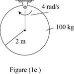
Refer Figure (1e).
Write the formula for mass moment of inertia
Here,
Write the formula for kinetic energy
Here,
Substitute
Here,
Conclusion:
Refer Figure (1e).
Calculate the kinetic energy of the disk.
Substitute
Thus, the kinetic energy of the disk is
f)
The kinetic energy of the object:
Answer to Problem 1PP
The kinetic energy of the disk is
Explanation of Solution
Given:
The mass of rod is
The angular velocity is
Draw the free body diagram of the object as shown in Figure (1f).
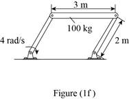
Refer Figure (1f).
Here, the ends of the rod are connected to two rods of same length. Hence the rod travels in circular motion.
Consider as the mass travels in a radius of
Write the formula for kinetic energy
(Rotation about fixed axis).
Here,
Substitute
Here,
Conclusion:
Refer Figure (1f).
Here
Calculate the kinetic energy of the disk.
Substitute
Thus, the kinetic energy of the disk is
Want to see more full solutions like this?
Chapter 18 Solutions
Engineering Mechanics: Dynamics (14th Edition)


- Question 1. Draw 3 teeth for the following pinion and gear respectively. The teeth should be drawn near the pressure line so that the teeth from the pinion should mesh those of the gear. Drawing scale (1:1). Either a precise hand drawing or CAD drawing is acceptable. Draw all the trajectories of the involute lines and the circles. Specification: 18tooth pinion and 30tooth gear. Diameter pitch=P=6 teeth /inch. Pressure angle:20°, 1/P for addendum (a) and 1.25/P for dedendum (b). For fillet, c=b-a.arrow_forward5. The figure shows a gear train. There is no friction at the bearings except for the gear tooth forces. The material of the milled gears is steel having a Brinell hardness of 170. The input shaft speed (n2) is 800 rpm. The face width and the contact angle for all gears are 1 in and 20° respectively. In this gear set, the endurance limit (Se) is 15 kpsi and nd (design factor) is 2. (a) Find the revolution speed of gear 5. (b) Determine whether each gear satisfies the design factor of 2.0 for bending fatigue. (c) Determine whether each gear satisfies the design factor of 2.0 for surface fatigue (contact stress). (d) According to the computation results of the questions (b) and (c), explain the possible failure mechanisms for each gear. N4=28 800rpm N₁=43 N5=34 N₂=14 P(diameteral pitch)=8 for all gears Coupled to 2.5hp motorarrow_forward1. The rotating steel shaft is simply supported by bearings at points of B and C, and is driven by a spur gear at D, which has a 6-in pitch diameter. The force F from the drive gear acts at a pressure angle of 20°. The shaft transmits a torque to point A of TA =3000 lbĘ in. The shaft is machined from steel with Sy=60kpsi and Sut=80 kpsi. (1) Draw a shear force diagram and a bending moment diagram by F. According to your analysis, where is the point of interest to evaluate the safety factor among A, B, C, and D? Describe the reason. (Hint: To find F, the torque Tд is generated by the tangential force of F (i.e. Ftangential-Fcos20°) When n=2.5, K=1.8, and K₁ =1.3, determine the diameter of the shaft based on (2) static analysis using DE theory (note that fatigue stress concentration factors need to be used for this question because the loading condition is fatigue) and (3) a fatigue analysis using modified Goodman. Note) A standard diameter is not required for the questions. 10 in Darrow_forward
- 3 N2=28 P(diametral pitch)=8 for all gears Coupled to 25 hp motor N3=34 Full depth spur gears with pressure angle=20° N₂=2000 rpm (1) Compute the circular pitch, the center-to-center distance, and base circle radii. (2) Draw the free body diagram of gear 3 and show all the forces and the torque. (3) In mounting gears, the center-to-center distance was reduced by 0.1 inch. Calculate the new values of center-to-center distance, pressure angle, base circle radii, and pitch circle diameters. (4)What is the new tangential and radial forces for gear 3? (5) Under the new center to center distance, is the contact ratio (mc) increasing or decreasing?arrow_forward2. A flat belt drive consists of two 4-ft diameter cast-iron pulleys spaced 16 ft apart. A power of 60 hp is transmitted by a pulley whose speed is 380 rev/min. Use a service factor (Ks) pf 1.1 and a design factor 1.0. The width of the polyamide A-3 belt is 6 in. Use CD=1. Answer the following questions. (1) What is the total length of the belt according to the given geometry? (2) Find the centrifugal force (Fc) applied to the belt. (3) What is the transmitted torque through the pulley system given 60hp? (4) Using the allowable tension, find the force (F₁) on the tight side. What is the tension at the loose side (F2) and the initial tension (F.)? (5) Using the forces, estimate the developed friction coefficient (f) (6) Based on the forces and the given rotational speed, rate the pulley set. In other words, what is the horse power that can be transmitted by the pulley system? (7) To reduce the applied tension on the tight side, the friction coefficient is increased to 0.75. Find out the…arrow_forwardThe tooth numbers for the gear train illustrated are N₂ = 24, N3 = 18, №4 = 30, №6 = 36, and N₁ = 54. Gear 7 is fixed. If shaft b is turned through 5 revolutions, how many turns will shaft a make? a 5 [6] barrow_forward
- Please do not use any AI tools to solve this question. I need a fully manual, step-by-step solution with clear explanations, as if it were done by a human tutor. No AI-generated responses, please.arrow_forwardPlease do not use any AI tools to solve this question. I need a fully manual, step-by-step solution with clear explanations, as if it were done by a human tutor. No AI-generated responses, please.arrow_forwardCE-112 please solve this problem step by step and give me the correct answerarrow_forward
 International Edition---engineering Mechanics: St...Mechanical EngineeringISBN:9781305501607Author:Andrew Pytel And Jaan KiusalaasPublisher:CENGAGE L