
College Physics:
11th Edition
ISBN: 9781305965515
Author: SERWAY, Raymond A.
Publisher: Brooks/Cole Pub Co
expand_more
expand_more
format_list_bulleted
Videos
Textbook Question
Chapter 18, Problem 55AP
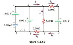
The circuit in Figure P18.55 has been connected for several seconds. Find the current (a) in the 4.00-V battery,(b) in the 3.00-Ω resistor,(c)in the 8.00-V battery, and (d)in the 3.00-V battery.(e)Find the charge on the capacitor.
Expert Solution & Answer

Trending nowThis is a popular solution!

Students have asked these similar questions
The circuit in Figure P18.55 has been connected for severalseconds. Find the current (a) in the 4.00 - V battery, (b) in the3.00 - Ω resistor, (c) in the 8.00 - V battery, and (d) in the 3.00 - Vbattery. (e) Find the charge on the capacitor.
A 2.1-µF capacitor is charged to 12 V and then discharged through a 4.9×10⁶ Ω resistor. How long (in seconds) will it take for the voltage across the capacitor to drop to 3.7 V?
A 10.0 μF capacitor is charged to 50.0 V and is then connected across a 460 Ω resistor only. What is the voltage across the resistor after 7.60 ms?
Chapter 18 Solutions
College Physics:
Ch. 18.1 - True or False: While discharging, the terminal...Ch. 18.1 - Why does a battery get warm while in use?Ch. 18.2 - In Figure 18.5, the current is measured with the...Ch. 18.2 - The circuit in Figure 18.5 consists of two...Ch. 18.3 - In Figure 18.8, the current is measured with the...Ch. 18.3 - When the switch is open in Figure 18.8, power Po...Ch. 18.3 - Suppose you have three identical lightbulbs, some...Ch. 18.3 - If the lightbulbs in Quick Quiz 18.7 are connected...Ch. 18.5 - The switch is closed in Figure 18.20. After a long...Ch. 18 - Choose the words that make each statement correct....
Ch. 18 - Given three lightbulbs and a battery, sketch as...Ch. 18 - Suppose the energy transferred to a dead battery...Ch. 18 - A short circuit is a circuit containing a path of...Ch. 18 - Electric current I enters a node with three...Ch. 18 - If electrical power is transmitted over long...Ch. 18 - The following statements are related to household...Ch. 18 - Two sets of Christmas lights are available. For...Ch. 18 - Why is it possible for a bird to sit on a...Ch. 18 - An uncharged series RC circuit is to be connected...Ch. 18 - Suppose a parachutist lands on a high-voltage wire...Ch. 18 - A ski resort consists of a few chairlifts and...Ch. 18 - Embodied in Kirchhoffs rules are two conservation...Ch. 18 - Why is it dangerous to turn on a light when you...Ch. 18 - A battery haring an emf of 9.00 V delivers 117 mA...Ch. 18 - Prob. 2PCh. 18 - A battery with an emf of 12.0 V has a terminal...Ch. 18 - A battery with a 0.100- internal resistance...Ch. 18 - Two resistors, R1 and R2 are connected in series....Ch. 18 - Three 9.0- resistors are connected in series with...Ch. 18 - (a) Find the equivalent resistance between points...Ch. 18 - Consider the combination of resistors shown in...Ch. 18 - Prob. 9PCh. 18 - Consider the circuit shown in Figure P18.10. (a)...Ch. 18 - Consider the circuit shown in Figure P18.11. Find...Ch. 18 - Four resistors are connected to a battery as shown...Ch. 18 - The resistance between terminals a and b in Figure...Ch. 18 - A battery with = 6.00 V and no internal...Ch. 18 - Find the current in the 12- resistor in Figure...Ch. 18 - (a) Is it possible to reduce the circuit shown in...Ch. 18 - (a) You need a 45- resistor, but the stockroom has...Ch. 18 - (a) Find the current in each resistor of Figure...Ch. 18 - Figure P18.19 shows a Wheatstone bridge, a circuit...Ch. 18 - For the circuit shown in Figure P18.20, calculate...Ch. 18 - Taking R = 1.00 k and = 250 V in Figure P18.21,...Ch. 18 - In the circuit of Figure P18.22, the current I1 is...Ch. 18 - In the circuit of Figure P18.23, determine (a) the...Ch. 18 - Four resistors are connected to a battery with a...Ch. 18 - Using Kirchhoffs rules (a) find the current in...Ch. 18 - Figure P18.26 shows a voltage divider, a circuit...Ch. 18 - (a) Can the circuit shown in Figure P18.27 be...Ch. 18 - A dead battery is charged by connecting it to the...Ch. 18 - (a) Can the circuit shown in Figure P18.29 be...Ch. 18 - For the circuit shown in Figure P18.30, use...Ch. 18 - Find the potential difference across each resistor...Ch. 18 - Show that = RC has units of time.Ch. 18 - Consider the series RC circuit shown in Figure...Ch. 18 - An uncharged capacitor and a resistor are...Ch. 18 - Consider a series RC circuit as in Figure P18.35...Ch. 18 - The RC charging circuit in a camera flash unit has...Ch. 18 - Figure P18.37 shows a simplified model of a...Ch. 18 - The capacitor in Figure P18.35 is uncharged for t ...Ch. 18 - What minimum number of 75-W light bulbs must be...Ch. 18 - A 1 150-W toaster and an 825-W microwave oven are...Ch. 18 - Prob. 41PCh. 18 - Prob. 42PCh. 18 - Assume a length of axon membrane of about 0.10 m...Ch. 18 - Consider the model of the axon as a capacitor from...Ch. 18 - Prob. 45PCh. 18 - How many different resistance values can be...Ch. 18 - (a) Calculate the potential difference between...Ch. 18 - For the circuit shown in Figure P18.48, the...Ch. 18 - Figure P18.49 shows separate series and parallel...Ch. 18 - Three 60.0-W, 120-V lightbulbs are connected...Ch. 18 - When two unknown resistors are connected in series...Ch. 18 - The circuit in Figure P18.52a consists of three...Ch. 18 - A circuit consists of three identical lamps, each...Ch. 18 - The resistance between points a and b in Figure...Ch. 18 - The circuit in Figure P18.55 has been connected...Ch. 18 - Prob. 56APCh. 18 - The student engineer of a campus radio station...Ch. 18 - The resistor R in Figure P18.58 dissipates 20 W of...Ch. 18 - A voltage V is applied to a series configuration...Ch. 18 - For the network in Figure P18.60, show that the...Ch. 18 - A battery with an internal resistance of 10.0 ...Ch. 18 - The circuit in Figure P18.62 contains two...Ch. 18 - An electric eel generates electric currents...Ch. 18 - In Figure P18.64, R1 = 0.100 , R2 = 1.00 , and R3...Ch. 18 - What are the expected readings of the ammeter and...Ch. 18 - Consider the two arrangements of batteries and...Ch. 18 - The given pair of capacitors in Figure P18.67 is...Ch. 18 - 2.00-nF capacitor with an initial charge of 5.10 C...
Knowledge Booster


Learn more about
Need a deep-dive on the concept behind this application? Look no further. Learn more about this topic, physics and related others by exploring similar questions and additional content below.Similar questions
- Consider the circuit shown in Figure P26.24, where C1, = 6.00 F, C2 = 3.00 F. and V = 20.0 V. Capacitor C1 is first charged by closing switch S1. Switch S1 is then opened, and the charged capacitor is connected to the uncharged capacitor by closing Calculate (a) the initial charge acquired by C, and (b) the final charge on each capacitor.arrow_forwardThe circuit in Figure P27.35 has been connected for several seconds. Find the current (a) in the 4.00-V battery, (b) in the 3.00- resistor, (c) in the 8.00-V battery, and (d) in the 3.00-V battery. (e) Find the charge on the capacitor. Figure P27.35arrow_forwardA battery is used to charge a capacitor through a resistor as shown in Figure P27.44. Show that half the energy supplied by the battery appears as internal energy in the resistor and half is stored in the capacitor. Figure P27.44arrow_forward
- Figure P18.26 shows a voltage divider, a circuit used to obtain a desired voltage Vout from a source voltage . Determine the required value of R2 if = 5.00 V, Vout = 1.50 V and R1 = 1.00 103 (Hint: Use Kirchhoff's loop rule, substituting Vout = IR2, to find the current. Then solve Ohms law for R2. Figure P18.26arrow_forwardConsider the circuit shown in Figure P20.52, where C1 = 6.00 F, C2 = 3.00 F, and V = 20.0 V. Capacitor C1 is first charged by closing switch S1. Switch S1 is then opened, and the charged capacitor is connected to the uncharged capacitor by closing S2. Calculate (a) the initial charge acquired by C1 and (b) the final charge on each capacitor. Figure P20.52arrow_forwardA charge Q is placed on a capacitor of capacitance C. The capacitor is connected into the circuit shown in Figure P26.37, with an open switch, a resistor, and an initially uncharged capacitor of capacitance 3C. The switch is then closed, and the circuit comes to equilibrium. In terms of Q and C, find (a) the final potential difference between the plates of each capacitor, (b) the charge on each capacitor, and (c) the final energy stored in each capacitor. (d) Find the internal energy appearing in the resistor. Figure P26.37arrow_forward
- Electric current I enters a node with three resistors connected in parallel (Fig. CQ18.5). Which one of the following is correct? (a) I1 = I and I2 = I3 = 0. (b) I2 I1 and I2 I3. (c) V1 V2 V3 (d) I1 I2 I3 0. Figure CQ18.5arrow_forwardA Pairs of parallel wires or coaxial cables are two conductors separated by an insulator, so they have a capacitance. For a given cable, the capacitance is independent of the length if the cable is very long. A typical circuit model of a cable is shown in Figure P27.87. It is called a lumped-parameter model and represents how a unit length of the cable behaves. Find the equivalent capacitance of a. one unit length (Fig. P27.87A), b. two unit lengths (Fig. P27.87B), and c. an infinite number of unit lengths (Fig. P27.87C). Hint: For the infinite number of units, adding one more unit at the beginning does not change the equivalent capacitance.arrow_forwardThe terminals of a battery are connected across two resistors in parallel. The resistances of the resistors are not the same. Which of the following statements is correct? Choose all that are correct. (a) The resistor with the larger resistance carries more current than the other resistor. (b) The resistor with the larger resistance carries less current than the other resistor. (c) The potential difference across each resistor is the same. (d) The potential difference across the larger resistor is greater than the potential difference across the smaller resistor. (e) The potential difference is greater across the resistor closer to the battery.arrow_forward
- The ammeter shown in Figure P21.45 reads 2.00 A. Find I1, I2, and . Figure P21.45arrow_forwardThe circuit in Figure P21.59 has been connected for a long time. (a) What is the potential difference across the capacitor? (b) If the battery is disconnected from the circuit, over what time interval does the capacitor discharge to one-tenth its initial voltage?arrow_forwardThe- pair of capacitors in Figure P28.63 are fully charged by a 12.0-V battery. The battery is disconnected, and the switch is then closed. Alter 1.00 ms has elapsed, (a) how much charge remains 011 the 3.00-F capacitor? (b) How much charge remains on the 2.00-F capacitor? (c) What is the current in the resistor at this time?arrow_forward
arrow_back_ios
SEE MORE QUESTIONS
arrow_forward_ios
Recommended textbooks for you
 College PhysicsPhysicsISBN:9781305952300Author:Raymond A. Serway, Chris VuillePublisher:Cengage Learning
 Physics for Scientists and Engineers with Modern ...PhysicsISBN:9781337553292Author:Raymond A. Serway, John W. JewettPublisher:Cengage Learning
 College PhysicsPhysicsISBN:9781285737027Author:Raymond A. Serway, Chris VuillePublisher:Cengage Learning
 Principles of Physics: A Calculus-Based TextPhysicsISBN:9781133104261Author:Raymond A. Serway, John W. JewettPublisher:Cengage Learning
 Physics for Scientists and Engineers, Technology ...PhysicsISBN:9781305116399Author:Raymond A. Serway, John W. JewettPublisher:Cengage Learning
 Physics for Scientists and EngineersPhysicsISBN:9781337553278Author:Raymond A. Serway, John W. JewettPublisher:Cengage Learning
College Physics
Physics
ISBN:9781305952300
Author:Raymond A. Serway, Chris Vuille
Publisher:Cengage Learning
Physics for Scientists and Engineers with Modern ...
Physics
ISBN:9781337553292
Author:Raymond A. Serway, John W. Jewett
Publisher:Cengage Learning
College Physics
Physics
ISBN:9781285737027
Author:Raymond A. Serway, Chris Vuille
Publisher:Cengage Learning
Principles of Physics: A Calculus-Based Text
Physics
ISBN:9781133104261
Author:Raymond A. Serway, John W. Jewett
Publisher:Cengage Learning
Physics for Scientists and Engineers, Technology ...
Physics
ISBN:9781305116399
Author:Raymond A. Serway, John W. Jewett
Publisher:Cengage Learning
Physics for Scientists and Engineers
Physics
ISBN:9781337553278
Author:Raymond A. Serway, John W. Jewett
Publisher:Cengage Learning
How To Solve Any Resistors In Series and Parallel Combination Circuit Problems in Physics; Author: The Organic Chemistry Tutor;https://www.youtube.com/watch?v=eFlJy0cPbsY;License: Standard YouTube License, CC-BY