
College Physics:
11th Edition
ISBN: 9781305965515
Author: SERWAY, Raymond A.
Publisher: Brooks/Cole Pub Co
expand_more
expand_more
format_list_bulleted
Videos
Textbook Question
Chapter 18, Problem 26P
Figure P18.26 shows a voltage divider, a circuit used to obtain a desired voltage ΔVout from a source voltage ε. Determine the required value of R2 if ε = 5.00 V, ΔVout = 1.50 V and R1 = 1.00 × 10³ Ω (Hint: Use Kirchhoff's loop rule, substituting ΔVout = IR2, to find the current. Then solve Ohm’s law for R2.
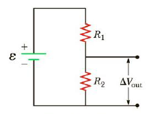
Figure P18.26
Expert Solution & Answer
Want to see the full answer?
Check out a sample textbook solution
Students have asked these similar questions
2
3
Imagine you are out for a stroll on a sunny day when you encounter a lake. Unpolarized light from the sun is reflected off the lake into your eyes. However, you notice when you put on your vertically polarized sunglasses, the light reflected off the lake no longer reaches your eyes. What is the angle between the unpolarized light and the surface of the water, in degrees, measured from the horizontal? You may assume the index of refraction of air is nair=1 and the index of refraction of water is nwater=1.33 . Round your answer to three significant figures. Just enter the number, nothing else.
Chapter 18 Solutions
College Physics:
Ch. 18.1 - True or False: While discharging, the terminal...Ch. 18.1 - Why does a battery get warm while in use?Ch. 18.2 - In Figure 18.5, the current is measured with the...Ch. 18.2 - The circuit in Figure 18.5 consists of two...Ch. 18.3 - In Figure 18.8, the current is measured with the...Ch. 18.3 - When the switch is open in Figure 18.8, power Po...Ch. 18.3 - Suppose you have three identical lightbulbs, some...Ch. 18.3 - If the lightbulbs in Quick Quiz 18.7 are connected...Ch. 18.5 - The switch is closed in Figure 18.20. After a long...Ch. 18 - Choose the words that make each statement correct....
Ch. 18 - Given three lightbulbs and a battery, sketch as...Ch. 18 - Suppose the energy transferred to a dead battery...Ch. 18 - A short circuit is a circuit containing a path of...Ch. 18 - Electric current I enters a node with three...Ch. 18 - If electrical power is transmitted over long...Ch. 18 - The following statements are related to household...Ch. 18 - Two sets of Christmas lights are available. For...Ch. 18 - Why is it possible for a bird to sit on a...Ch. 18 - An uncharged series RC circuit is to be connected...Ch. 18 - Suppose a parachutist lands on a high-voltage wire...Ch. 18 - A ski resort consists of a few chairlifts and...Ch. 18 - Embodied in Kirchhoffs rules are two conservation...Ch. 18 - Why is it dangerous to turn on a light when you...Ch. 18 - A battery haring an emf of 9.00 V delivers 117 mA...Ch. 18 - Prob. 2PCh. 18 - A battery with an emf of 12.0 V has a terminal...Ch. 18 - A battery with a 0.100- internal resistance...Ch. 18 - Two resistors, R1 and R2 are connected in series....Ch. 18 - Three 9.0- resistors are connected in series with...Ch. 18 - (a) Find the equivalent resistance between points...Ch. 18 - Consider the combination of resistors shown in...Ch. 18 - Prob. 9PCh. 18 - Consider the circuit shown in Figure P18.10. (a)...Ch. 18 - Consider the circuit shown in Figure P18.11. Find...Ch. 18 - Four resistors are connected to a battery as shown...Ch. 18 - The resistance between terminals a and b in Figure...Ch. 18 - A battery with = 6.00 V and no internal...Ch. 18 - Find the current in the 12- resistor in Figure...Ch. 18 - (a) Is it possible to reduce the circuit shown in...Ch. 18 - (a) You need a 45- resistor, but the stockroom has...Ch. 18 - (a) Find the current in each resistor of Figure...Ch. 18 - Figure P18.19 shows a Wheatstone bridge, a circuit...Ch. 18 - For the circuit shown in Figure P18.20, calculate...Ch. 18 - Taking R = 1.00 k and = 250 V in Figure P18.21,...Ch. 18 - In the circuit of Figure P18.22, the current I1 is...Ch. 18 - In the circuit of Figure P18.23, determine (a) the...Ch. 18 - Four resistors are connected to a battery with a...Ch. 18 - Using Kirchhoffs rules (a) find the current in...Ch. 18 - Figure P18.26 shows a voltage divider, a circuit...Ch. 18 - (a) Can the circuit shown in Figure P18.27 be...Ch. 18 - A dead battery is charged by connecting it to the...Ch. 18 - (a) Can the circuit shown in Figure P18.29 be...Ch. 18 - For the circuit shown in Figure P18.30, use...Ch. 18 - Find the potential difference across each resistor...Ch. 18 - Show that = RC has units of time.Ch. 18 - Consider the series RC circuit shown in Figure...Ch. 18 - An uncharged capacitor and a resistor are...Ch. 18 - Consider a series RC circuit as in Figure P18.35...Ch. 18 - The RC charging circuit in a camera flash unit has...Ch. 18 - Figure P18.37 shows a simplified model of a...Ch. 18 - The capacitor in Figure P18.35 is uncharged for t ...Ch. 18 - What minimum number of 75-W light bulbs must be...Ch. 18 - A 1 150-W toaster and an 825-W microwave oven are...Ch. 18 - Prob. 41PCh. 18 - Prob. 42PCh. 18 - Assume a length of axon membrane of about 0.10 m...Ch. 18 - Consider the model of the axon as a capacitor from...Ch. 18 - Prob. 45PCh. 18 - How many different resistance values can be...Ch. 18 - (a) Calculate the potential difference between...Ch. 18 - For the circuit shown in Figure P18.48, the...Ch. 18 - Figure P18.49 shows separate series and parallel...Ch. 18 - Three 60.0-W, 120-V lightbulbs are connected...Ch. 18 - When two unknown resistors are connected in series...Ch. 18 - The circuit in Figure P18.52a consists of three...Ch. 18 - A circuit consists of three identical lamps, each...Ch. 18 - The resistance between points a and b in Figure...Ch. 18 - The circuit in Figure P18.55 has been connected...Ch. 18 - Prob. 56APCh. 18 - The student engineer of a campus radio station...Ch. 18 - The resistor R in Figure P18.58 dissipates 20 W of...Ch. 18 - A voltage V is applied to a series configuration...Ch. 18 - For the network in Figure P18.60, show that the...Ch. 18 - A battery with an internal resistance of 10.0 ...Ch. 18 - The circuit in Figure P18.62 contains two...Ch. 18 - An electric eel generates electric currents...Ch. 18 - In Figure P18.64, R1 = 0.100 , R2 = 1.00 , and R3...Ch. 18 - What are the expected readings of the ammeter and...Ch. 18 - Consider the two arrangements of batteries and...Ch. 18 - The given pair of capacitors in Figure P18.67 is...Ch. 18 - 2.00-nF capacitor with an initial charge of 5.10 C...
Knowledge Booster


Learn more about
Need a deep-dive on the concept behind this application? Look no further. Learn more about this topic, physics and related others by exploring similar questions and additional content below.Similar questions
- 20. Two small conducting spheres are placed on top of insulating pads. The 3.7 × 10⁻¹⁰ C sphere is fixed whie the 3.0 × 10⁷ C sphere, initially at rest, is free to move. The mass of each sphere is 0.09 kg. If the spheres are initially 0.10 m apart, how fast will the sphere be moving when they are 1.5 m apart?arrow_forwardpls help on allarrow_forwardpls help on thesearrow_forward
- pls help on all asked questions kindlyarrow_forwardpls help on all asked questions kindlyarrow_forward19. Mount Everest, Earth's highest mountain above sea level, has a peak of 8849 m above sea level. Assume that sea level defines the height of Earth's surface. (re = 6.38 × 10⁶ m, ME = 5.98 × 1024 kg, G = 6.67 × 10 -11 Nm²/kg²) a. Calculate the strength of Earth's gravitational field at a point at the peak of Mount Everest. b. What is the ratio of the strength of Earth's gravitational field at a point 644416m below the surface of the Earth to a point at the top of Mount Everest? C. A tourist watching the sunrise on top of Mount Everest observes a satellite orbiting Earth at an altitude 3580 km above his position. Determine the speed of the satellite.arrow_forward
- pls help on allarrow_forwardpls help on allarrow_forward6. As the distance between two charges decreases, the magnitude of the electric potential energy of the two-charge system: a) Always increases b) Always decreases c) Increases if the charges have the same sign, decreases if they have the opposite signs d) Increases if the charges have the opposite sign, decreases if they have the same sign 7. To analyze the motion of an elastic collision between two charged particles we use conservation of & a) Energy, Velocity b) Momentum, Force c) Mass, Momentum d) Energy, Momentum e) Kinetic Energy, Potential Energyarrow_forward
arrow_back_ios
SEE MORE QUESTIONS
arrow_forward_ios
Recommended textbooks for you
 Principles of Physics: A Calculus-Based TextPhysicsISBN:9781133104261Author:Raymond A. Serway, John W. JewettPublisher:Cengage Learning
 Physics for Scientists and EngineersPhysicsISBN:9781337553278Author:Raymond A. Serway, John W. JewettPublisher:Cengage Learning
 Physics for Scientists and Engineers with Modern ...PhysicsISBN:9781337553292Author:Raymond A. Serway, John W. JewettPublisher:Cengage Learning
 College PhysicsPhysicsISBN:9781285737027Author:Raymond A. Serway, Chris VuillePublisher:Cengage Learning
 College PhysicsPhysicsISBN:9781305952300Author:Raymond A. Serway, Chris VuillePublisher:Cengage Learning
Principles of Physics: A Calculus-Based Text
Physics
ISBN:9781133104261
Author:Raymond A. Serway, John W. Jewett
Publisher:Cengage Learning
Physics for Scientists and Engineers
Physics
ISBN:9781337553278
Author:Raymond A. Serway, John W. Jewett
Publisher:Cengage Learning
Physics for Scientists and Engineers with Modern ...
Physics
ISBN:9781337553292
Author:Raymond A. Serway, John W. Jewett
Publisher:Cengage Learning
College Physics
Physics
ISBN:9781285737027
Author:Raymond A. Serway, Chris Vuille
Publisher:Cengage Learning
College Physics
Physics
ISBN:9781305952300
Author:Raymond A. Serway, Chris Vuille
Publisher:Cengage Learning
DC Series circuits explained - The basics working principle; Author: The Engineering Mindset;https://www.youtube.com/watch?v=VV6tZ3Aqfuc;License: Standard YouTube License, CC-BY