
Concept explainers
Videos
Refer to Figure 18.9. A cantilever sheet pile is driven into a granular soil where the water table is 2 m (L1) below the top of the sand. The properties of the sand are
Find the required actual depth of the sheet pile.
Answer to Problem 18.1P
The required actual depth of the sheet pile is
Explanation of Solution
Given information:
The depth of water level below the sand
The angle of internal friction for sand
The unit weight of the sand
The saturated unit weight of the sand
The depth below the ground level (L) is 6 m.
Calculation:
Show the cross section of cantilever sheet pile with dimensions as in Figure (1).
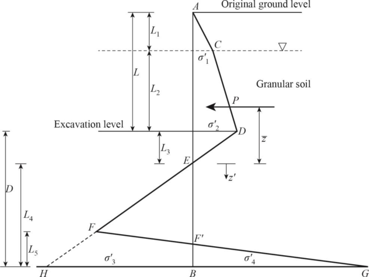
Refer Figure (1),
Find the depth of water table level
Find the rankine active pressure coefficient
Find the rankine passive pressure coefficient
Find the difference between the rankine active pressure coefficient and rankine passive pressure coefficient:
Find the effective unit weight of sand
At the water table level:
Find the intensity of the active pressure to the right of the pile
At the excavation level:
Find the intensity of the active pressure to the right of the pile
Find the depth below the dredge line
Find the area of the pressure diagram (P):
Find the area of the pressure diagram into center of pressure
Find the center of pressure to the area
Find the intensity of the passive pressure
Find the area
Find the area
Find the area
Find the area
Find the depth below point E
Use trial and error method to calculate depth below point E
Try
Substitute 4.30 m for
Hence, the assumption is correct.
The depth below point E is 4.30 m.
Find the depth below the dredge line to bottom of the pile (D):
Increase the depth below the dredge line to bottom of the pile by 30%. The depth below the dredge line to bottom of the pile (D) is 6.214 m.
Find required actual depth of the sheet pile
Thus, the required actual depth of the sheet pile is
Want to see more full solutions like this?
Chapter 18 Solutions
Principles of Foundation Engineering (MindTap Course List)


- u(t) (Uss) -1 a/w = 1.0 M 1 2 3 Tarrow_forwardplease helparrow_forwardPlease use MATLAB with codes and figures.Recreate the following four Figures of the textbook using MATLAB and the appropriate parameters. Comment on your observations for each Figure. List all of the parameters that you have used. The figures are attached belowarrow_forward
- A simply supported beam for a building interior with 18 ft span has a cross section of 12 in width and 21 in overall depth. The beam is made with 5 ksi compressive strength concrete and 60 ksi reinforcing steel. The beam supports a uniform service superimposed dead load of 1.6 kip/ft, and a uniform service live load of 80 psf throughout the span. The beams are laterally spaced 20 ft apart c/c. Design this beam and show in a sketch.arrow_forwardThe dam presented below is 180 m long (in the direction perpendicular to the plane of the cross-section). For the water elevations given on the drawing: a) Construct the flow net (minimum number of equipotential lines should be 10), b) Calculate the rate of seepage for the entire dam, c) Find the total uplift force on the dam (ignore barriers), and d) Estimate the hydraulic gradient at points A, B, and D. Recommended to use a spreadsheet to include all equations for calculations of potentials.arrow_forwardUsing A36 steel select the lightest equal leg single angle member to resist a factored (LRFD) tensile load Pu = 167 kips. The member will be connected through one leg with one line of three 3/4-in Ø bolts spaced at 3 in between centers as shown. The edge distances Leh = Lev = 1.5 in. Use LRFD Method Use U from Table D3.1, Case 8. See attached (D3.1 Case 8, Shear Strength of Bolts, Table 1-7 Dimensions of Angles).arrow_forward
- The system in Fig. consists of 1200 m of 5 cm cast-iron pipe e=0.26mm, two 45° and four 90° elbows, a globe valve, and a sharp exit into a reservoir. If the elevation at point 1 is 400 m, what gage pressure is required at point 1 to deliver 0.005 m3/s of water into the reservoir? U= 10-6m² 1 * sec -, K 45° elbows= 0.2, K 90° flanged = 0.2, K globe valve 10, K Sharp exit=1 G Elevation 500 m 45° Open globe 45° Sharp exitarrow_forward: The 6-cm-diameter pipe in Fig. contains glycerin [specific gravity 0.95], flowing at a rate of 6 m³/h. Verify that the flow is laminar. For the pressure measurements shown, is the flow up or down? What is the indicated head loss for these pressures? 3.7 atm B 2.1 atm 12 m Aarrow_forwardFind the discharge if K entrance =0.1, Kvalve-1, e=0.26mm, U= 1× 10⁻⁶m² ? sec 5 m Water at 20°C 6 cm D=5cm, L 2 m Open jet Butterfly valve DC 107 at 30°arrow_forward
- What level (h) must be maintained in Fig to deliver a flow rate of Q=0.425L/sec in commercial-steel pipe e=0.1mm, U= 1 * 10-6m²/sec? Water at 20°C h L=24m D=120mmarrow_forward17-24. Design a water distribution system for the Village of Waffle (Figure P-17-24). The specific de- sign requirements of the client are as follows: 128 m Figure P-17-24 Village of Waffle. -120 m 120 m Open in new tab 00 N ☐ Pancake Road D Apartments ☐ DD. D ☐ 128 m Coffee Creek DODQ00000 Eggs Road State Road 00000 ㅁㅁㅁㅁㅁㅁ Syrup River _128 m 136 m 120 m ㅁㅁㅁ Syrup River 112 m 104 m 100-Year flood -112 m 120 m- 128 m Water tower Grd El 137 m 100 m Share a. Fire protection to be provided by the water distribution system. b. Minimum water pressure at top of apartment building is to be 240 kPa. c. Maximum system pressure is to be 550 kPa. The following assumptions may be used in the design: a. Each of the four apartment buildings is occupied by 50 residents. Each apartment building is four stories high. Each story is 3 m high. b. Each house is occupied by three residents. c. Average daily demand for the village is 500 Lpcd. d. Peaking factor is 6.2 for peak hour demand. e. Needed fire flow…arrow_forwardTwo group of students are collecting traffic data at the two sections A and B 200 meters apartalong a highway. Group A shows that 5 vehicles pass those sections at interval of 8, 9, 10, 11and 13 sections respectively. If the speeds of the vehicles were 80, 72, 64, 56 and 48 kmph.Compute : (i) the time mean speed (ii) space mean speed, and (b)what will be the averagedensity of the above traffic streamarrow_forward
 Principles of Foundation Engineering (MindTap Cou...Civil EngineeringISBN:9781305081550Author:Braja M. DasPublisher:Cengage Learning
 Fundamentals of Geotechnical Engineering (MindTap...Civil EngineeringISBN:9781305635180Author:Braja M. Das, Nagaratnam SivakuganPublisher:Cengage Learning
 Principles of Foundation Engineering (MindTap Cou...Civil EngineeringISBN:9781337705028Author:Braja M. Das, Nagaratnam SivakuganPublisher:Cengage Learning
 Principles of Geotechnical Engineering (MindTap C...Civil EngineeringISBN:9781305970939Author:Braja M. Das, Khaled SobhanPublisher:Cengage Learning