Concept explainers
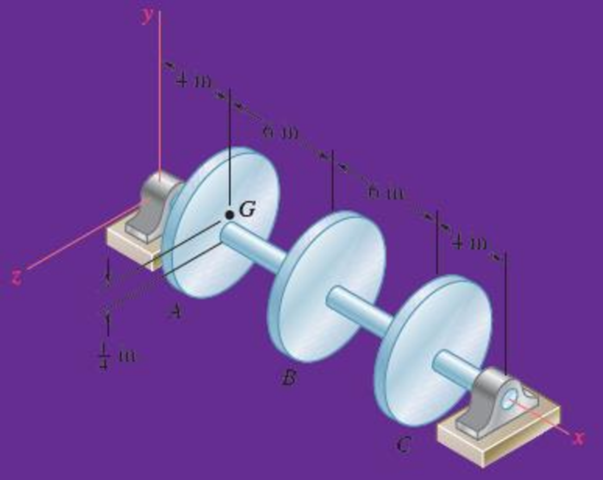
Three 25-lb rotor disks are attached to a shaft that rotates at 720 rpm. Disk A is attached eccentrically so that its mass center is

Fig. P18.147
Where should 2 lb weights be bolted to disks B and C to balance the system dynamically.
Answer to Problem 18.147RP
The 2 lb weights be bolted to disks B and C to balance the system dynamically are
Explanation of Solution
Given Information:
The weight (W) of the disk is 25 lb.
The shaft rotates at 720 rpm.
The mass center of the disk A is
Calculation:
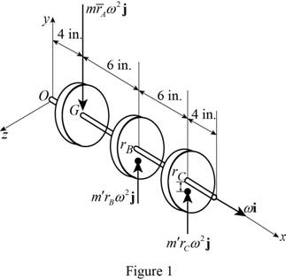
Draw the free body diagram of the system as shown in Figure (1).

The angular velocity of the shaft is constant. So, the rate of change of angular momentum is zero.
Express the effective force
Here,
Express the effective force
Express the effective force
The sum of the effective forces of the discs should be equal to zero for the system to be in dynamic balance.
Substitute
Substitute
According to principle of impulse momentum, the total momentum is zero.
Express the moment about O:
Here,
Substitute
Substitute
Multiply Equation (1) by
The 2 lb weight is be placed above the shaft for disk C.
Substitute
The 2 lb weight is be placed below the shaft for disk B.
Thus, the 2 lb weights be bolted to disks B and C to balance the system dynamically are
Want to see more full solutions like this?
Chapter 18 Solutions
VECTOR MECHANIC
- No chatgpt plsarrow_forwardA six cylinder petrol engine has a compression ratio of 5:1. The clearance volume of each cylinder is 110CC. It operates on the four-stroke constant volume cycle and the indicated efficiency ratio referred to air standard efficiency is 0.56. At the speed of 2400 rpm. 44000KJ/kg. Determine the consumes 10kg of fuel per hour. The calorific value of fuel average indicated mean effective pressure.arrow_forwardThe members of a truss are connected to the gusset plate as shown in (Figure 1). The forces are concurrent at point O. Take = 90° and T₁ = 7.5 kN. Part A Determine the magnitude of F for equilibrium. Express your answer to three significant figures and include the appropriate units. F= 7.03 Submit ? kN Previous Answers Request Answer × Incorrect; Try Again; 21 attempts remaining ▾ Part B Determine the magnitude of T2 for equilibrium. Express your answer to three significant figures and include the appropriate units. Figure T₂ = 7.03 C T2 |? KN Submit Previous Answers Request Answer × Incorrect; Try Again; 23 attempts remaining Provide Feedbackarrow_forward
- Consider the following acid-base reaction: Fe3+(aq) +3H2O -Fe(OH)3 (s) + 3H* ← A. Using thermodynamics, calculate the equilibrium constant K at 25°C (The AG° of formation of Fe(OH)3(s) is -699 kJ/mol). B. Using the value of K you calculated in part a, if a solution contains 10-4 M Fe3+ and has a pH of 7.5, will Fe(OH)3(s) precipitate? Show all calculations necessary to justify your answer. Note that the reaction as written is for precipitation, not dissolution like Ksp-arrow_forwardA vertical force of F = 3.4 kN is applied to the hook at A as shown in. Set d = 1 m. Part A 3 m 3m 0.75 m 1.5 m. Determine the tension in cable AB for equilibrium. Express your answer to three significant figures and include the appropriate units. FAB= Value Submit Request Answer Part B Units ? Determine the tension in cable AC for equilibrium. Express your answer to three significant figures and include the appropriate units. FAC = Value Submit Request Answer Part C ? Units Determine the tension in cable AD for equilibrium. Express your answer to three significant figures and include the appropriate units.arrow_forwardConsider the heat engine operating at steady state between the two thermal reservoirs shown at the right while producing a net power output of 700 kW. If 1000 kW of heat (Q̇H) is transferred to the heat engine from a thermal reservoir at a temperature of TH = 900 K, and heat is rejected to a thermal reservoir at a temperature of TL = 300 K, is this heat engine possible? Can you answer this question for me and show all of the workarrow_forward
- 1.12 A disk of constant radius r is attached to a telescoping rod that is extending at a constant rate as shown in Fig. P1.12. Both the disk and the rod are rotating at a constant rate. Find the inertial velocity and acceleration of point P at the rim of the disk. ท2 L 0 SS P α e 0 O' êL Fig. P1.12 Rotating disk attached to telescoping rod. 60 LLarrow_forwardTwo different options A and B with brake pads for disc brakes are connected to the rope drum. The diameter of the rope drum is 150 mm. What distance must the pads B be at from the center of rotation to cover the same distance as A?A B- Width 50 mm - Width 60 mm- Evidence center 120mm - Construction power 900 N from rotation center.- Maintains a weight of 200 kgwhen the installation force is 1.4kN (μ is missing from the data)M=μF(Ry-Ri)Right answer R=187 mmarrow_forwardAssume the xy plane is level ground, and that the vertical pole shown in the diagram lies along the z-axis with its base at the origin. If the pole is 5 m tall, and a rope is used to pull on the top of the pole with a force of 400 N as shown, determine the magnitudes of the parallel and perpendicular components of the force vector with respect to the axis of the post i.e. with respect to the z-axis.arrow_forward
- 4-1 Q4: Q5: (20 Marks) Find √48 using False Position Method with three iterations. Hint: the root lies between 3 and 4. (20 Marks)arrow_forwardDetermine the angle between vectors FA and FB that is less than 180 degrees. FA is the vector drawn from the origin to point A (-4, 4, 2) while FB is the vector drawn from the origin to point B (3, 1, -3).arrow_forwardFind the resultant force vector from adding F1, F2 and F3, where … F1 = {-8i+10j-32k} N F2 is 40 N in magnitude with coordinate direction angles α, β, and γ, of 45, 120 and 60 degrees, respectively and F3 is 22 N in magnitude with transverse and azimuth angles of 65 and 40 degrees, respectively Express your final answer as a Cartesian vector as well as a magnitude with angles.arrow_forward
 Elements Of ElectromagneticsMechanical EngineeringISBN:9780190698614Author:Sadiku, Matthew N. O.Publisher:Oxford University Press
 Mechanics of Materials (10th Edition)Mechanical EngineeringISBN:9780134319650Author:Russell C. HibbelerPublisher:PEARSON
 Thermodynamics: An Engineering ApproachMechanical EngineeringISBN:9781259822674Author:Yunus A. Cengel Dr., Michael A. BolesPublisher:McGraw-Hill Education
 Control Systems EngineeringMechanical EngineeringISBN:9781118170519Author:Norman S. NisePublisher:WILEY
 Mechanics of Materials (MindTap Course List)Mechanical EngineeringISBN:9781337093347Author:Barry J. Goodno, James M. GerePublisher:Cengage Learning
 Engineering Mechanics: StaticsMechanical EngineeringISBN:9781118807330Author:James L. Meriam, L. G. Kraige, J. N. BoltonPublisher:WILEY


