
Fundamentals of Electric Circuits
6th Edition
ISBN: 9780078028229
Author: Charles K Alexander, Matthew Sadiku
Publisher: McGraw-Hill Education
expand_more
expand_more
format_list_bulleted
Videos
Textbook Question
Chapter 17.8, Problem 14PP
Rework Example 17.14 if the low-pass filter is replaced by the ideal bandpass filter shown in Fig. 17.46.
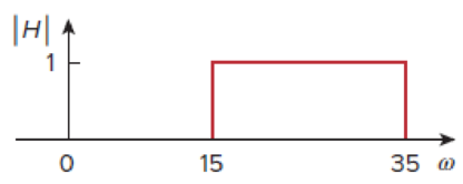
Figure 17.46
Example 17.14
If the sawtooth waveform in Fig. 17.45(a) is applied to an ideal low-pass filter with the transfer function shown in Fig. 17.45(b), determine the output.
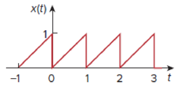
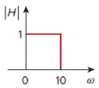
Figure 17.45
Expert Solution & Answer
Want to see the full answer?
Check out a sample textbook solution
Students have asked these similar questions
Don't use ai to answer I will report you answer
A 3-phase, 50 Hz, 132 kV overhead line transpose system of bundle conductors .a radius of
conductor is 0.5 cm. Calculate the total inductance of the line.
bi
4m
Im
cl
4m
bir
A single phase has two group A and B, 50 Hz, overhead line system has radius of conductor 0.5 cm.
Calculate the total inductance of the line
21
A
a2
b₂
4 m
B
b₁
3m
6 cm
2 m
Chapter 17 Solutions
Fundamentals of Electric Circuits
Ch. 17.2 - Find the Fourier series of the square wave in Fig....Ch. 17.2 - Determine the Fourier series of the sawtooth...Ch. 17.3 - Prob. 3PPCh. 17.3 - Find the Fourier series expansion of the function...Ch. 17.3 - Prob. 5PPCh. 17.4 - Prob. 6PPCh. 17.4 - If the input voltage in the circuit of Fig. 17.24...Ch. 17.5 - The voltage and current at the terminals of a...Ch. 17.5 - Find the rms value of the periodic current i(t) =...Ch. 17.6 - Obtain the complex Fourier series of the function...
Ch. 17.6 - Obtain the complex Fourier series expansion of...Ch. 17.7 - Prob. 12PPCh. 17.8 - Rework Example 17.14 if the low-pass filter is...Ch. 17 - Which of the following cannot be a Fourier series?...Ch. 17 - If ft=t,0t,ft+n=ft, the value of 0 is (a) 1 (b) 2...Ch. 17 - Which of the following are even functions? (a) t +...Ch. 17 - Prob. 4RQCh. 17 - Prob. 5RQCh. 17 - If f(t) = 10 + 8 cos t + 4 cos 3t + 2 cos 5t + ,...Ch. 17 - Prob. 7RQCh. 17 - The plot of |cn| versus n0 is called: (a) complex...Ch. 17 - Prob. 9RQCh. 17 - Prob. 10RQCh. 17 - Evaluate each of the following functions and see...Ch. 17 - Using MATLAB, synthesize the periodic waveform for...Ch. 17 - Given that Fourier coefficients a0, an, and bn of...Ch. 17 - Find the Fourier series expansion of the backward...Ch. 17 - Prob. 5PCh. 17 - Find the trigonometric Fourier series for f t =...Ch. 17 - Determine the Fourier series of the periodic...Ch. 17 - Using Fig. 17.51, design a problem to help other...Ch. 17 - Determine the Fourier coefficients an and bn of...Ch. 17 - Find the exponential Fourier series for the...Ch. 17 - Obtain the exponential Fourier series for the...Ch. 17 - Prob. 12PCh. 17 - Prob. 13PCh. 17 - Find the quadrature (cosine and sine) form of the...Ch. 17 - Express the Fourier series...Ch. 17 - The waveform in Fig. 17.55(a) has the following...Ch. 17 - Prob. 17PCh. 17 - Prob. 18PCh. 17 - Obtain the Fourier series for the periodic...Ch. 17 - Prob. 20PCh. 17 - Prob. 21PCh. 17 - Calculate the Fourier coefficients for the...Ch. 17 - Using Fig. 17.61, design a problem to help other...Ch. 17 - Prob. 24PCh. 17 - Determine the Fourier series representation of the...Ch. 17 - Find the Fourier series representation of the...Ch. 17 - For the waveform shown in Fig. 17.65 below, (a)...Ch. 17 - Obtain the trigonometric Fourier series for the...Ch. 17 - Prob. 29PCh. 17 - Prob. 30PCh. 17 - Prob. 31PCh. 17 - Prob. 32PCh. 17 - Prob. 33PCh. 17 - Prob. 34PCh. 17 - Prob. 35PCh. 17 - Prob. 36PCh. 17 - If the periodic current waveform in Fig. 17.73(a)...Ch. 17 - Prob. 38PCh. 17 - Prob. 39PCh. 17 - The full-wave rectified sinusoidal voltage in Fig....Ch. 17 - Prob. 42PCh. 17 - The voltage across the terminals of a circuit is...Ch. 17 - Prob. 44PCh. 17 - A series RLC circuit has R = 10 , L = 2 mH, and C...Ch. 17 - Prob. 46PCh. 17 - Prob. 47PCh. 17 - Prob. 48PCh. 17 - Prob. 49PCh. 17 - Prob. 50PCh. 17 - Prob. 51PCh. 17 - Prob. 52PCh. 17 - Prob. 53PCh. 17 - Find the exponential Fourier series for the...Ch. 17 - Obtain the exponential Fourier series expansion of...Ch. 17 - The Fourier series trigonometric representation of...Ch. 17 - Prob. 57PCh. 17 - Find the exponential Fourier series of a function...Ch. 17 - Prob. 59PCh. 17 - Obtain the complex Fourier coefficients of the...Ch. 17 - The spectra of the Fourier series of a function...Ch. 17 - Prob. 62PCh. 17 - Plot the amplitude spectrum for the signal f2(t)...Ch. 17 - Prob. 64PCh. 17 - Prob. 65PCh. 17 - Prob. 66PCh. 17 - Prob. 67PCh. 17 - Prob. 68PCh. 17 - Prob. 69PCh. 17 - Design a problem to help other students better...Ch. 17 - Prob. 71PCh. 17 - Prob. 72PCh. 17 - Prob. 73PCh. 17 - Prob. 74PCh. 17 - Prob. 75PCh. 17 - Prob. 76PCh. 17 - Prob. 77CPCh. 17 - Prob. 78CPCh. 17 - Consider the full-wave rectified sinusoidal...Ch. 17 - Prob. 82CP
Knowledge Booster


Learn more about
Need a deep-dive on the concept behind this application? Look no further. Learn more about this topic, electrical-engineering and related others by exploring similar questions and additional content below.Similar questions
- In a single phase below, conductors a₁ and a₂ are in parallel form one circuit while conductors b₁ and b₂ in parallel form the return path. Calculate the total inductance of the line per km assuming that current is equally shared by the two parallel conductors. Conductor diameter in 2-0 cm. a₁ az b₁ b₂ 100 cm 20 cm 20 cmarrow_forwardDon't use ai to answer I will report you answerarrow_forwardDon't use ai to answer I will report you answerarrow_forward
- 4. Discussion: GINEE Compare between theoretical combination effect of Kp and KD at first order and second order systems regarding steady-state errors and transient responses with the practical obtained results whenever applying step input signalın Experiment PD controller و المهندسة الكهربائيةarrow_forwardDon't use ai to answer I will report you answerarrow_forwardDon't use ai to answer I will report you answerarrow_forward
- Plot the magnitude spectrum analytically predict by the equation below: n=∞ s(t) = Σ In (ß) cos[2π(fc +nfm)t] n=-∞ fc = 1MHz fm = 10 kHz B = 5arrow_forwardb C Is 3601116-67 Bre ✓ BIb ≤5K 20k e 0-25K 7. Zo Z Zb B=100, Ble=1Kr Zb=S & Zin = S, Zo=S, AV=Sarrow_forwardDon't use ai to answer I will report you answerarrow_forward
arrow_back_ios
SEE MORE QUESTIONS
arrow_forward_ios
Recommended textbooks for you
 Introductory Circuit Analysis (13th Edition)Electrical EngineeringISBN:9780133923605Author:Robert L. BoylestadPublisher:PEARSON
 Delmar's Standard Textbook Of ElectricityElectrical EngineeringISBN:9781337900348Author:Stephen L. HermanPublisher:Cengage Learning
 Programmable Logic ControllersElectrical EngineeringISBN:9780073373843Author:Frank D. PetruzellaPublisher:McGraw-Hill Education
 Fundamentals of Electric CircuitsElectrical EngineeringISBN:9780078028229Author:Charles K Alexander, Matthew SadikuPublisher:McGraw-Hill Education
 Electric Circuits. (11th Edition)Electrical EngineeringISBN:9780134746968Author:James W. Nilsson, Susan RiedelPublisher:PEARSON
 Engineering ElectromagneticsElectrical EngineeringISBN:9780078028151Author:Hayt, William H. (william Hart), Jr, BUCK, John A.Publisher:Mcgraw-hill Education,
Introductory Circuit Analysis (13th Edition)
Electrical Engineering
ISBN:9780133923605
Author:Robert L. Boylestad
Publisher:PEARSON
Delmar's Standard Textbook Of Electricity
Electrical Engineering
ISBN:9781337900348
Author:Stephen L. Herman
Publisher:Cengage Learning
Programmable Logic Controllers
Electrical Engineering
ISBN:9780073373843
Author:Frank D. Petruzella
Publisher:McGraw-Hill Education
Fundamentals of Electric Circuits
Electrical Engineering
ISBN:9780078028229
Author:Charles K Alexander, Matthew Sadiku
Publisher:McGraw-Hill Education
Electric Circuits. (11th Edition)
Electrical Engineering
ISBN:9780134746968
Author:James W. Nilsson, Susan Riedel
Publisher:PEARSON
Engineering Electromagnetics
Electrical Engineering
ISBN:9780078028151
Author:Hayt, William H. (william Hart), Jr, BUCK, John A.
Publisher:Mcgraw-hill Education,
Notation and Basic Signal Properties; Author: Barry Van Veen;https://www.youtube.com/watch?v=2_Pl25nFhr4;License: Standard Youtube License