
Vector Mechanics for Engineers: Statics and Dynamics
12th Edition
ISBN: 9781259638091
Author: Ferdinand P. Beer, E. Russell Johnston Jr., David Mazurek, Phillip J. Cornwell, Brian Self
Publisher: McGraw-Hill Education
expand_more
expand_more
format_list_bulleted
Concept explainers
Videos
Textbook Question
Chapter 17.1, Problem 17.4P
Two disks of the same material are attached to a shaft as shown. Disk A has a radius r and a thickness b, while disk B has a radius nr and a thickness 2b. A couple M with a constant magnitude is applied when the system is at rest and is removed after the system has executed two revolutions. Determine the value of n that results in the largest final speed for a point on the rim of disk B.
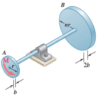
Fig. P17.3 and P17.4
Expert Solution & Answer
Want to see the full answer?
Check out a sample textbook solution
Students have asked these similar questions
In a structural reliability problem, the resistance (capacity) R and load effect (demand) S random variables
associated with a failure mode of the structure of interest are normally distributed and statistically
independent with the following probability distribution parameters (or statistics) in consistent units:
MR = 12, σR = 3
μs = 5, σs = 2
(a) Determine the exact probability of failure pF ·
The resistance R and load effect S for a given failure mode are statistically independent random variables
with marginal PDF's
1
fR (r) =
0≤r≤100
100'
fs(s)=0.05e-0.05s
(a) Determine the probability of failure by computing the probability content of the failure domain defined
as {r
Please solve this problem as soon as possible My ID# 016948724
Chapter 17 Solutions
Vector Mechanics for Engineers: Statics and Dynamics
Ch. 17.1 - A round object of mass m and radius r is released...Ch. 17.1 - Prob. 17.2CQCh. 17.1 - Prob. 17.3CQCh. 17.1 - Prob. 17.4CQCh. 17.1 - Slender bar A is rigidly connected to a massless...Ch. 17.1 - A 200-kg flywheel is at rest when a constant 300...Ch. 17.1 - The rotor of an electric motor has an angular...Ch. 17.1 - Prob. 17.3PCh. 17.1 - Two disks of the same material are attached to a...Ch. 17.1 - The flywheel of a punching machine has a weight of...
Ch. 17.1 - Prob. 17.6PCh. 17.1 - Prob. 17.7PCh. 17.1 - Prob. 17.8PCh. 17.1 - The 10-in.-radius brake drum is attached to a...Ch. 17.1 - Prob. 17.10PCh. 17.1 - Each of the gears A and B has a mass of 10 kg and...Ch. 17.1 - Solve Prob. 17.11, assuming that the 6 Nm couple...Ch. 17.1 - Prob. 17.13PCh. 17.1 - The double pulley shown has a mass of 15 kg and a...Ch. 17.1 - Gear A has a mass of 1 kg and a radius of gyration...Ch. 17.1 - A slender rod of length l and mass m is pivoted...Ch. 17.1 - The 15-kg rear hatch of a vehicle opens as shown...Ch. 17.1 - A slender 9-lb rod can rotate in a vertical plane...Ch. 17.1 - An adapted golf device attaches to a wheelchair to...Ch. 17.1 - A 10-kg storm window measuring 900 1500 mm is...Ch. 17.1 - A collar with a mass of 1 kg is rigidly attached...Ch. 17.1 - A collar with a mass of 1 kg is rigidly attached...Ch. 17.1 - Two identical slender rods AB and BC are welded...Ch. 17.1 - Prob. 17.24PCh. 17.1 - A 100-kg solid cylindrical disk, 800 mm in...Ch. 17.1 - Prob. 17.26PCh. 17.1 - Greek engineers had the unenviable task of moving...Ch. 17.1 - A small sphere of mass m and radius r is released...Ch. 17.1 - Prob. 17.29PCh. 17.1 - A half-cylinder with mass m and radius r is...Ch. 17.1 - Prob. 17.31PCh. 17.1 - Two uniform cylinders, each of weight W = 14 lb...Ch. 17.1 - Prob. 17.33PCh. 17.1 - A bar of mass m = 5 kg is held as shown between...Ch. 17.1 - The 1.5-kg uniform slender bar AB is connected to...Ch. 17.1 - The motion of the uniform rod AB is guided by...Ch. 17.1 - Prob. 17.37PCh. 17.1 - Prob. 17.38PCh. 17.1 - The ends of a 9-lb rod AB are constrained to move...Ch. 17.1 - The mechanism shown is one of two identical...Ch. 17.1 - The mechanism shown is one of two identical...Ch. 17.1 - Each of the two rods shown is of length L = 1 m...Ch. 17.1 - The 4-kg rod AB is attached to a collar of...Ch. 17.1 - If in Prob. 17.43 the angular velocity of the...Ch. 17.1 - The uniform rods AB and BC are of mass 3 kg and 8...Ch. 17.1 - The uniform rods AB and BC weigh 2.4 kg and 4 kg,...Ch. 17.1 - The 80-mm-radius gear shown has a mass of 5 kg and...Ch. 17.1 - Prob. 17.48PCh. 17.1 - Three shafts and four gears are used to form a...Ch. 17.1 - The experimental setup shown is used to measure...Ch. 17.1 - Prob. 17.51PCh. 17.2 - The 350-kg flywheel of a small hoisting engine has...Ch. 17.2 - Prob. 17.2IMDCh. 17.2 - Prob. 17.3IMDCh. 17.2 - Prob. 17.52PCh. 17.2 - A bolt located 2 in. from the center of an...Ch. 17.2 - A small grinding wheel is attached to the shaft of...Ch. 17.2 - A uniform 144-lb cube is attached to a uniform...Ch. 17.2 - Prob. 17.56PCh. 17.2 - Prob. 17.57PCh. 17.2 - Prob. 17.58PCh. 17.2 - Prob. 17.59PCh. 17.2 - Each of the double pulleys shown has a centroidal...Ch. 17.2 - Each of the gears A and B has a mass of 675 g and...Ch. 17.2 - Two identical uniform cylinders of mass m and...Ch. 17.2 - Two identical 16-lb uniform cylinders of radius r...Ch. 17.2 - Prob. 17.64PCh. 17.2 - Prob. 17.65PCh. 17.2 - Show that, when a rigid body rotates about a fixed...Ch. 17.2 - Prob. 17.68PCh. 17.2 - A flywheel is rigidly attached to a 1.5-in.-radius...Ch. 17.2 - A wheel of radius r and centroidal radius of...Ch. 17.2 - Prob. 17.71PCh. 17.2 - 17.72 and 17.73The 3-lb carriage C is supported as...Ch. 17.2 - Prob. 17.73PCh. 17.2 - Two uniform cylinders, each of mass m = 6 kg and...Ch. 17.2 - Prob. 17.75PCh. 17.2 - Prob. 17.76PCh. 17.2 - A sphere of radius r and mass m is projected along...Ch. 17.2 - A bowler projects an 8.5-in.-diameter ball...Ch. 17.2 - Prob. 17.79PCh. 17.2 - A satellite has a total weight (on Earth) of 250...Ch. 17.2 - Two 10-lb disks and a small motor are mounted on a...Ch. 17.2 - Prob. 17.82PCh. 17.2 - Prob. 17.83PCh. 17.2 - Prob. 17.84PCh. 17.2 - Prob. 17.85PCh. 17.2 - Prob. 17.86PCh. 17.2 - The 30-kg uniform disk A and the bar BC are at...Ch. 17.2 - Prob. 17.88PCh. 17.2 - A 1.8-kg collar A and a 0.7-kg collar B can slide...Ch. 17.2 - Prob. 17.90PCh. 17.2 - A small 4-lb collar C can slide freely on a thin...Ch. 17.2 - Rod AB has a weight of 6 lb and is attached to a...Ch. 17.2 - A 3-kg uniform cylinder A can roll without sliding...Ch. 17.2 - The 4-kg cylinder B and the 3-kg wedge A are at...Ch. 17.2 - The 6-lb steel cylinder A of radius r and the...Ch. 17.3 - A uniform slender rod AB of mass m is at rest on a...Ch. 17.3 - Prob. 17.5IMDCh. 17.3 - Prob. 17.6IMDCh. 17.3 - At what height h above its center G should a...Ch. 17.3 - A bullet weighing 0.08 lb is fired with a...Ch. 17.3 - In Prob. 17.97, determine (a) the required...Ch. 17.3 - A 16-lb wooden panel is suspended from a pin...Ch. 17.3 - Prob. 17.100PCh. 17.3 - A 45-g bullet is fired with a velocity of 400 m/s...Ch. 17.3 - A 45-g bullet is fired with a velocity of 400 m/s...Ch. 17.3 - The tire shown has a radius R = 300 mm and a...Ch. 17.3 - Prob. 17.104PCh. 17.3 - A uniform slender rod AB of mass m is at rest on a...Ch. 17.3 - A uniform slender rod AB is at rest on a...Ch. 17.3 - A bullet of mass m is fired with a horizontal...Ch. 17.3 - Determine the height h at which the bullet of...Ch. 17.3 - A uniform slender bar of length L = 200 mm and...Ch. 17.3 - A uniform slender rod of length L is dropped onto...Ch. 17.3 - A uniform slender rod AB has a mass m, a length L,...Ch. 17.3 - You have been hired to design a baseball catcher...Ch. 17.3 - The trapeze/lanyard air drop (t/LAD) launch is a...Ch. 17.3 - The uniform rectangular block shown is moving...Ch. 17.3 - The 40-kg gymnast drops from her maximum height of...Ch. 17.3 - A uniform slender rod AB of length L = 600 mm is...Ch. 17.3 - Prob. 17.118PCh. 17.3 - A 1-oz bullet is fired with a horizontal velocity...Ch. 17.3 - For the beam of Prob. 17.119, determine the...Ch. 17.3 - Prob. 17.121PCh. 17.3 - Prob. 17.122PCh. 17.3 - A slender rod AB is released from rest in the...Ch. 17.3 - Prob. 17.124PCh. 17.3 - Block A has a mass m and is attached to a cord...Ch. 17.3 - Prob. 17.126PCh. 17.3 - 17.127 and 17.128Member ABC has a mass of 2.4 kg...Ch. 17.3 - 17.127 and 17.128Member ABC has a mass of 2.4 kg...Ch. 17.3 - Prob. 17.129PCh. 17.3 - Prob. 17.130PCh. 17.3 - A small rubber ball of radius r is thrown against...Ch. 17.3 - Sphere A of mass m and radius r rolls without...Ch. 17.3 - In a game of pool, ball A is rolling without...Ch. 17 - A uniform disk, initially at rest and of constant...Ch. 17 - The 8-in.-radius brake drum is attached to a...Ch. 17 - A uniform slender rod is placed at corner B and is...Ch. 17 - The motion of the slender 250-mm rod AB is guided...Ch. 17 - A baseball attachment that helps people with...Ch. 17 - Disks A and B are made of the same material, are...Ch. 17 - Disks A and B are made of the same material, are...
Knowledge Booster


Learn more about
Need a deep-dive on the concept behind this application? Look no further. Learn more about this topic, mechanical-engineering and related others by exploring similar questions and additional content below.Similar questions
- The gears shown in the figure have a diametral pitch of 2 teeth per inch and a 20° pressure angle. The pinion rotates at 1800 rev/min clockwise and transmits 200 hp through the idler pair to gear 5 on shaft c. What forces do gears 3 and 4 transmit to the idler shaft? TS I y 18T 32T This a 12 x 18T C 48T 5arrow_forwardQuestion 1. Draw 3 teeth for the following pinion and gear respectively. The teeth should be drawn near the pressure line so that the teeth from the pinion should mesh those of the gear. Drawing scale (1:1). Either a precise hand drawing or CAD drawing is acceptable. Draw all the trajectories of the involute lines and the circles. Specification: 18tooth pinion and 30tooth gear. Diameter pitch=P=6 teeth /inch. Pressure angle:20°, 1/P for addendum (a) and 1.25/P for dedendum (b). For fillet, c=b-a.arrow_forward5. The figure shows a gear train. There is no friction at the bearings except for the gear tooth forces. The material of the milled gears is steel having a Brinell hardness of 170. The input shaft speed (n2) is 800 rpm. The face width and the contact angle for all gears are 1 in and 20° respectively. In this gear set, the endurance limit (Se) is 15 kpsi and nd (design factor) is 2. (a) Find the revolution speed of gear 5. (b) Determine whether each gear satisfies the design factor of 2.0 for bending fatigue. (c) Determine whether each gear satisfies the design factor of 2.0 for surface fatigue (contact stress). (d) According to the computation results of the questions (b) and (c), explain the possible failure mechanisms for each gear. N4=28 800rpm N₁=43 N5=34 N₂=14 P(diameteral pitch)=8 for all gears Coupled to 2.5hp motorarrow_forward
- 1. The rotating steel shaft is simply supported by bearings at points of B and C, and is driven by a spur gear at D, which has a 6-in pitch diameter. The force F from the drive gear acts at a pressure angle of 20°. The shaft transmits a torque to point A of TA =3000 lbĘ in. The shaft is machined from steel with Sy=60kpsi and Sut=80 kpsi. (1) Draw a shear force diagram and a bending moment diagram by F. According to your analysis, where is the point of interest to evaluate the safety factor among A, B, C, and D? Describe the reason. (Hint: To find F, the torque Tд is generated by the tangential force of F (i.e. Ftangential-Fcos20°) When n=2.5, K=1.8, and K₁ =1.3, determine the diameter of the shaft based on (2) static analysis using DE theory (note that fatigue stress concentration factors need to be used for this question because the loading condition is fatigue) and (3) a fatigue analysis using modified Goodman. Note) A standard diameter is not required for the questions. 10 in Darrow_forward3 N2=28 P(diametral pitch)=8 for all gears Coupled to 25 hp motor N3=34 Full depth spur gears with pressure angle=20° N₂=2000 rpm (1) Compute the circular pitch, the center-to-center distance, and base circle radii. (2) Draw the free body diagram of gear 3 and show all the forces and the torque. (3) In mounting gears, the center-to-center distance was reduced by 0.1 inch. Calculate the new values of center-to-center distance, pressure angle, base circle radii, and pitch circle diameters. (4)What is the new tangential and radial forces for gear 3? (5) Under the new center to center distance, is the contact ratio (mc) increasing or decreasing?arrow_forward2. A flat belt drive consists of two 4-ft diameter cast-iron pulleys spaced 16 ft apart. A power of 60 hp is transmitted by a pulley whose speed is 380 rev/min. Use a service factor (Ks) pf 1.1 and a design factor 1.0. The width of the polyamide A-3 belt is 6 in. Use CD=1. Answer the following questions. (1) What is the total length of the belt according to the given geometry? (2) Find the centrifugal force (Fc) applied to the belt. (3) What is the transmitted torque through the pulley system given 60hp? (4) Using the allowable tension, find the force (F₁) on the tight side. What is the tension at the loose side (F2) and the initial tension (F.)? (5) Using the forces, estimate the developed friction coefficient (f) (6) Based on the forces and the given rotational speed, rate the pulley set. In other words, what is the horse power that can be transmitted by the pulley system? (7) To reduce the applied tension on the tight side, the friction coefficient is increased to 0.75. Find out the…arrow_forward
- The tooth numbers for the gear train illustrated are N₂ = 24, N3 = 18, №4 = 30, №6 = 36, and N₁ = 54. Gear 7 is fixed. If shaft b is turned through 5 revolutions, how many turns will shaft a make? a 5 [6] barrow_forwardCE-112 please solve this problem step by step and give me the correct answerarrow_forwardCE-112 please solve this problem step by step and give me the correct answerarrow_forward
- CE-112 solve this problem step by step and give me the correct answer pleasearrow_forwardPlease do not use any AI tools to solve this question. I need a fully manual, step-by-step solution with clear explanations, as if it were done by a human tutor. No AI-generated responses, please.arrow_forwardPlease do not use any AI tools to solve this question. I need a fully manual, step-by-step solution with clear explanations, as if it were done by a human tutor. No AI-generated responses, please.arrow_forward
arrow_back_ios
SEE MORE QUESTIONS
arrow_forward_ios
Recommended textbooks for you
 International Edition---engineering Mechanics: St...Mechanical EngineeringISBN:9781305501607Author:Andrew Pytel And Jaan KiusalaasPublisher:CENGAGE L
 Principles of Heat Transfer (Activate Learning wi...Mechanical EngineeringISBN:9781305387102Author:Kreith, Frank; Manglik, Raj M.Publisher:Cengage Learning
International Edition---engineering Mechanics: St...
Mechanical Engineering
ISBN:9781305501607
Author:Andrew Pytel And Jaan Kiusalaas
Publisher:CENGAGE L
Principles of Heat Transfer (Activate Learning wi...
Mechanical Engineering
ISBN:9781305387102
Author:Kreith, Frank; Manglik, Raj M.
Publisher:Cengage Learning
Mechanical Design (Machine Design) Clutches, Brakes and Flywheels Intro (S20 ME470 Class 15); Author: Professor Ted Diehl;https://www.youtube.com/watch?v=eMvbePrsT34;License: Standard Youtube License