
Concept explainers
Videos
A slender rod of length l and mass m is pivoted about a point C located at a distance b from its center G. It is released from rest in a horizontal position and swings freely. Determine (a) the angular velocity of the rod as it passes through a vertical position if b = l/2, (b) the distance b for which the angular velocity of the rod as it passes through a vertical position is maximum, (c) the corresponding values of its angular velocity and of the reaction at C using the value of b calculated.
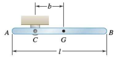
Fig. P17.16
(a)
Find the angular velocity of the rod when
Answer to Problem 17.16P
The angular velocity of the rod when
Explanation of Solution
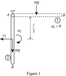
Show the free-body diagram of the given condition as in Figure 1.
Find the mass moment of inertia of the slender rod
Here, the mass of the slender rod is m and the length of the slender rod is l.
Position 1 (Horizontal position):
The angular velocity
The velocity
Find the total kinetic energy in the horizontal position
Substitute 0 for
Positon 2 (Vertical position):
Find the velocity of the slender rod
Find the total kinetic energy in the vertical position
Substitute
Find the work done
Here, the acceleration due to gravity is g.
Write the equation of work and energy for the system using the equation.
Substitute 0 for
Therefore, the angular velocity of the rod when
(b)
Find the distance b for which the angular velocity of rod as it passes through a vertical position is maximum.
Answer to Problem 17.16P
The distance b for which the angular velocity of the rod is maximum in vertical position is
Explanation of Solution
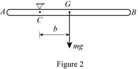
Position 1 (Horizontal position):
Show the free-body diagram of the horizontal position as in Figure 2.
Find the mass moment of inertia of the slender rod
The angular velocity
The velocity
Find the total kinetic energy in the horizontal position
Substitute 0 for
The elevation (h) of the pivot C is zero.
Find the total potential energy
Substitute 0 for h.
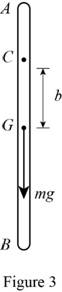
Positon 2 (Vertical position):
Show the free-body diagram of the vertical position as in Figure 3.
Find the velocity of the slender rod
Find the total kinetic energy in the vertical position
Substitute
The elevation of the pivot C is
Find the total potential energy
Substitute b for h.
Write the equation of conservation of energy using the equation.
Substitute 0 for
Integrate the angular velocity with respect to b and equate to zero.
Therefore, the distance b for which the angular velocity of the rod is maximum in vertical position is
(c)
Find the angular velocity where the vertical position is maximum and the reaction at pivot C.
Answer to Problem 17.16P
The angular velocity corresponding to the maximum vertical position is
The reaction at pivot C is
Explanation of Solution
Refer to the calculation of part (b):
Substitute
Therefore, the angular velocity corresponding to the maximum vertical position is
Show the free-body diagram of the slender rod as in Figure 4.
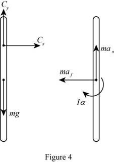
Find the normal acceleration
Substitute
The value of tangential acceleration is
Resolve the vertical component of forces.
Take moment about point C as follows;
Therefore,
Resolve the horizontal component of forces.
Find the resultant reaction at point C using the relation.
Substitute 0 for
Therefore, the reaction at pivot C is
Want to see more full solutions like this?
Chapter 17 Solutions
<LCPO> VECTOR MECH,STAT+DYNAMICS
Additional Engineering Textbook Solutions
Automotive Technology: Principles, Diagnosis, And Service (6th Edition) (halderman Automotive Series)
BASIC BIOMECHANICS
Database Concepts (8th Edition)
Concepts Of Programming Languages
Mechanics of Materials (10th Edition)
Thermodynamics: An Engineering Approach


- (Read Image)arrow_forwardM16x2 grade 8.8 bolts No. 25 C1- Q.2. The figure is a cross section of a grade 25 cast-iron pressure vessel. A total of N, M16x2.0 grade 8.8 bolts are to be used to resist a separating force of 160 kN. (a) Determine ks, km, and C. (b) Find the number of bolts required for a load factor of 2 where the bolts may be reused when the joint 19 mm is taken apart. (c) with the number of bolts obtained in (b), determine the realized load factor for overload, the yielding factor of safety, and the separation factor of safety. 19 mmarrow_forwardProblem4. The thin uniform disk of mass m = 1-kg and radius R = 0.1m spins about the bent shaft OG with the angular speed w2 = 20 rad/s. At the same time, the shaft rotates about the z-axis with the angular speed 001 = 10 rad/s. The angle between the bent portion of the shaft and the z-axis is ẞ = 35°. The mass of the shaft is negligible compared to the mass of the disk. a. Find the angular momentum of the disk with respect to point G, based on the axis orientation as shown. Include an MVD in your solution. b. Find the angular momentum of the disk with respect to point O, based on the axis orientation as shown. (Note: O is NOT the center of fixed-point rotation.) c. Find the kinetic energy of the assembly. z R R 002 2R x Answer: H = -0.046ĵ-0.040 kg-m²/sec Ho=-0.146-0.015 kg-m²/sec T 0.518 N-m =arrow_forward
- Problem 3. The assembly shown consists of a solid sphere of mass m and the uniform slender rod of the same mass, both of which are welded to the shaft. The assembly is rotating with angular velocity w at a particular moment. Find the angular momentum with respect to point O, in terms of the axes shown. Answer: Ñ。 = ½mc²wcosßsinßĵ + (}{mr²w + 2mb²w + ½ mc²wcos²ß) k 3 m r b 2 C لا marrow_forwardOnly question 2arrow_forwardOnly question 1arrow_forward
- Only question 3arrow_forwardI have Euler parameters that describe the orientation of N relative to Q, e = -0.7071*n3, e4 = 0.7071. I have Euler parameters that describe the orientation of U relative to N, e = -1/sqrt(3)*n1, e4 = sqrt(2/3). After using euler parameter rule of successive rotations, I get euler parameters that describe the orientation of U relative to Q, e = -0.4082*n1 - 0.4082*n2 - 0.5774*n3. I need euler parameters that describe the orientation of U relative to Q in vector basis of q instead of n. How do I get that?arrow_forwardDescribe at least 4 processes in engineering where control charts are (or should be) appliedarrow_forward
- Describe at least two (2) processes where control charts are (or should be) applied.arrow_forwardProblem 3: A cube-shaped spacecraft is in a circular Earth orbit. Let N (n,) be inertial and the spacecraft is denoted S (ŝ₁). The spacecraft is described such that ¯½º = J ŝ₁ŝ₁ + J ŝ₂§₂ + J §¸Ŝ3 Location of the spacecraft in the orbit is determined by the orbit-fixed unit vectors ê, that are oriented by the angle (Qt), where is a constant angular rate. 52 €3 3> 2t 55 Λ Из At the instant when Qt = 90°, the spacecraft S is oriented relative to the orbit such that 8₁ = 0° Space-three 1-2-3 angles 0₂ = 60° and ES = $₂ rad/s 0₁ = 135° (a) At this instant, determine the direction cosine matrix that describes the orientation of the spacecraft with respect to the inertial frame N.arrow_forwardThis problem illustrates that the factor of safety for a machine element depends on the particular point selected for analysis. Here you are to compute factors of safety, based upon the distortion-energy theory, for stress elements at A and B of the member shown in the figure. This bar is made of AISI 1006 cold-drawn steel and is loaded by the forces F = 1.100 kN, P = 8.00 kN, and T = 50.00 N-m. Given: Sy = 280 MPa. B -100 mm- 15-mm D. a) Determine the value of the axial stress at point B. b) Determine the value of the shear stress at point B. c) Determine the value of the Von Mises stress at point B. P Farrow_forward
 Elements Of ElectromagneticsMechanical EngineeringISBN:9780190698614Author:Sadiku, Matthew N. O.Publisher:Oxford University Press
 Mechanics of Materials (10th Edition)Mechanical EngineeringISBN:9780134319650Author:Russell C. HibbelerPublisher:PEARSON
 Thermodynamics: An Engineering ApproachMechanical EngineeringISBN:9781259822674Author:Yunus A. Cengel Dr., Michael A. BolesPublisher:McGraw-Hill Education
 Control Systems EngineeringMechanical EngineeringISBN:9781118170519Author:Norman S. NisePublisher:WILEY
 Mechanics of Materials (MindTap Course List)Mechanical EngineeringISBN:9781337093347Author:Barry J. Goodno, James M. GerePublisher:Cengage Learning
 Engineering Mechanics: StaticsMechanical EngineeringISBN:9781118807330Author:James L. Meriam, L. G. Kraige, J. N. BoltonPublisher:WILEY