
Concept explainers
Videos
Assume that the circuit shown in Figure 17-2 is connected to a 480-V, 60-Hz line. The inductor has an inductance of 0.053 H, and the resistor has a resistance of 12
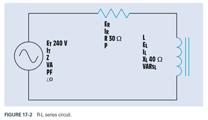
FIGURE 17-2 R-L series circuit.
Want to see the full answer?
Check out a sample textbook solution
Chapter 17 Solutions
Delmar's Standard Textbook Of Electricity


- A student organization has 12 members. A committee of 5members needs to be selected. How many ways can the committee be formed?arrow_forwardA fair coin is flipped 10 times. What is the probability that the coin lands on heads exactly 6 times?arrow_forwardA machine produces screws, and each screw has a 10% chance of being defective. A customer orders a batch of 25 screws. What is the probability that no more than 2 screws are defective in the batch?arrow_forward
- Q29arrow_forward1. Consider a pendulum consisting of two point masses on a single rod as shown below. The external torque acting on the pendulum is u(t). Suppose, the damping coefficient of the frictional toque is b. Find the nonlinear differential equation for the pendulum angle 0. marrow_forward4. Consider the following fluid system consisting of two tanks. Bult) Assume, R = 10, p = 1, g = 10 and ẞ = 1. a) Find the differential equation of the system. b) Find the transfer function (s) U(s)arrow_forward
 Power System Analysis and Design (MindTap Course ...Electrical EngineeringISBN:9781305632134Author:J. Duncan Glover, Thomas Overbye, Mulukutla S. SarmaPublisher:Cengage Learning
 Electricity for Refrigeration, Heating, and Air C...Mechanical EngineeringISBN:9781337399128Author:Russell E. SmithPublisher:Cengage Learning