Engineering Mechanics: Dynamics (14th Edition)
14th Edition
ISBN: 9780133915389
Author: Russell C. Hibbeler
Publisher: PEARSON
expand_more
expand_more
format_list_bulleted
Concept explainers
Videos
Textbook Question
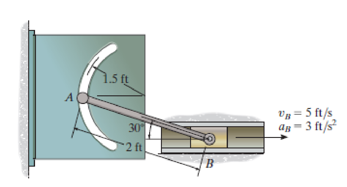
Chapter 16.8, Problem 128P
Determine the acceleration of A at the instant shown.
Expert Solution & Answer
Want to see the full answer?
Check out a sample textbook solution
Students have asked these similar questions
Qu 1 If crank OA rotates with an angular velocity of ω = 12 rad/s, determine the velocity of piston B and
the angular velocity of rod AB at the instant shown.
please show all work
Q2/ Maria has an online shop where she sells hand made paintings and
cards. She sells the painting for 50 and the card for 20. It takes her 2 hours
to complete 1 painting and 45 minutes to make a single card. She also has
a day job and makes paintings and cards in her free time. She cannot spend
more than 15 hours a week to make paintings and cards. Additionally, she
should make not more than 10 paintings and cards per week.
She makes a profit of 25 on painting and 15 on each card. How many
paintings and cards should she make each week to maximize her profit.
For the beam and loading shown, (a) draw the shear and bending moment diagrams, (b) determine the magnitude and location of the maximum absolute value of the bending momentConsider A = 0please show step by step process, i did something wrong with bending moment diagram( length of beam = 2 + 6 + 2)
Chapter 16 Solutions
Engineering Mechanics: Dynamics (14th Edition)
Ch. 16.3 - Determine its constant angular acceleration and...Ch. 16.3 - Determine the angular acceleration when it has...Ch. 16.3 - Determine the time it takes to achieve an angular...Ch. 16.3 - If the angular displacement of the wheel is =...Ch. 16.3 - Determine the magnitude of the velocity and...Ch. 16.3 - Determine the velocity of the cylinder and the...Ch. 16.3 - Determine the magnitudes of the velocity and...Ch. 16.3 - If the disk is originally rotating at 0 = 12...Ch. 16.3 - It it is subjected to a constant angular...Ch. 16.3 - If it is subjected to a constant angular...
Ch. 16.3 - Determine the number of revolutions, the angular...Ch. 16.3 - Determine the number of revolutions it must...Ch. 16.3 - Also, find the number of revolutions of gear D to...Ch. 16.3 - Gears A, B, C, and D have radii of 15 mm, 50 mm,...Ch. 16.3 - Determine the magnitude of acceleration of point B...Ch. 16.3 - pulley A is given a constant angular acceleration...Ch. 16.3 - Starting from rest, determine the angular...Ch. 16.3 - If the engine turns pulley A at A = (20t + 40)...Ch. 16.3 - If the engine turns pulley A at A = 60 rad/s,...Ch. 16.3 - Determine the angular velocity of the disk and its...Ch. 16.3 - Determine the magnitudes of the normal and...Ch. 16.3 - Determine the magnitudes of the normal and...Ch. 16.3 - If this gear is initially turning at A = 15 rad/s,...Ch. 16.3 - If this gear is initially turning at A = 15 rad/s,...Ch. 16.3 - Determine the brushs angular velocity when t = 4...Ch. 16.3 - If this gear is initially turning at (A)0 = 20...Ch. 16.3 - Determine the magnitudes of the velocity and the n...Ch. 16.3 - If the motor turns gear A with an angular...Ch. 16.3 - If the motor turns gear A with an angular...Ch. 16.3 - and the meshed pinion gear B on the propeller...Ch. 16.3 - determine the magnitude of the velocity and...Ch. 16.3 - If the gears A and have the dimensions shown,...Ch. 16.3 - and the meshed pinion gear B on the propeller...Ch. 16.3 - and the meshed pinion gear B on the propeller...Ch. 16.3 - If the canisters are centered 200 mm apart on the...Ch. 16.3 - Determine the largest angular velocity of gear B...Ch. 16.3 - The shaft of the motor M turns with an angular...Ch. 16.3 - If A has a constant angular acceleration of A = 30...Ch. 16.3 - If the angular displacement of A it A = (5t3 +...Ch. 16.3 - This gear is connected to gear B, which is fixed...Ch. 16.3 - Express the result in Cartesian vector form.Ch. 16.3 - Determine the velocity and acceleration of point D...Ch. 16.3 - At the instant shown it is rotating about the y...Ch. 16.3 - Determine the magnitudes of the velocity and...Ch. 16.4 - Determine the angular velocity and angular...Ch. 16.4 - Determine the angular acceleration and angular...Ch. 16.4 - Determine the angular acceleration and angular...Ch. 16.4 - Determine the angular velocity and angular...Ch. 16.4 - Determine the angular velocity of the connecting...Ch. 16.4 - The cam rotates with a constant counterclockwise...Ch. 16.4 - The pin connection at O does not cause an...Ch. 16.4 - Determine the velocity of the follower rod AB as...Ch. 16.4 - The pin connection at O does not cause an...Ch. 16.4 - Determine the velocity and acceleration of the peg...Ch. 16.4 - Determine the velocity and acceleration of block...Ch. 16.4 - Determine the angular velocity and angular...Ch. 16.4 - If the slotted arm is causing A to move downward...Ch. 16.4 - If the wedge moves to the left with a constant...Ch. 16.4 - If the rollers do not slip, determine their...Ch. 16.4 - If no slipping occurs between the disk D and the...Ch. 16.4 - Determine the velocity and acceleration of...Ch. 16.5 - If roller A moves to the right with a constant...Ch. 16.5 - Determine the magnitude of the velocity of point B...Ch. 16.5 - The cable wraps around the inner core, and the...Ch. 16.5 - If crank OA rotates with an angular velocity of =...Ch. 16.5 - If rod AB slides along the horizontal slot with a...Ch. 16.5 - Determine the velocity of the peg at B at this...Ch. 16.5 - Determine the velocity of point B at this instant.Ch. 16.5 - If the block at C is moving downward at 4 ft/s,...Ch. 16.5 - Determine the velocity of block C and the angular...Ch. 16.5 - Determine the angular velocities of links A B and...Ch. 16.5 - Also, sketch the position of link BC when = 55,...Ch. 16.5 - Link BC rotates clockwise with an angular velocity...Ch. 16.5 - If the angular velocity of link AB is AB = 3...Ch. 16.5 - Determine the velocity of the gear rack C.Ch. 16.5 - If B is moving to the right at 8 ft/s and C is...Ch. 16.5 - Determine the angular velocity of the gear and the...Ch. 16.5 - Determine the velocity of point A on the rim of...Ch. 16.5 - Link CB is horizontal at this instant.Ch. 16.5 - Determine the velocity of the slider C at the...Ch. 16.5 - Determine the velocity of block C and the angular...Ch. 16.5 - If AB has an angular velocity AB = 8 rad/s,...Ch. 16.5 - If the slider block A is moving downward at vA = 4...Ch. 16.5 - If the slider block A is moving downward at A = 4...Ch. 16.5 - This gear has an inner hub C which is fixed to B...Ch. 16.5 - If link AB is rotating at AB =3 rad/s, determine...Ch. 16.5 - If link CD is rotating at CD = 5 rad/s, determine...Ch. 16.5 - By locking or releasing certain gears, it has the...Ch. 16.5 - If the ring gear A rotates clockwise with an...Ch. 16.5 - It consists of a driving piston A, three links,...Ch. 16.5 - Because of the rotational motion of lint AB and...Ch. 16.6 - Establish the location of the instantaneous center...Ch. 16.6 - Determine the angular velocity of the rod and the...Ch. 16.6 - Determine the angular velocity of link BC and...Ch. 16.6 - The gear rack B is fixed.Ch. 16.6 - If cable AB is unwound with a speed of 3 m/s, and...Ch. 16.6 - Determine the angular velocity of link BC and the...Ch. 16.6 - Determine the angular velocity of links BC and CD...Ch. 16.6 - Assume the geometry is known.Ch. 16.6 - Determine the angular velocity of link AB at the...Ch. 16.6 - Determine the angular velocity of the link CB at...Ch. 16.6 - Determine the velocities of the cylinders center C...Ch. 16.6 - Determine the velocities of points A and B on the...Ch. 16.6 - Determine the velocities of points A and B.Ch. 16.6 - If rod CD is rotating with an angular velocity CD...Ch. 16.6 - If bar AB has an angular velocity AB = 6 rad/s,...Ch. 16.6 - Under these conditions, what is the speed at A if...Ch. 16.6 - Due to slipping, points A and B on the rim of the...Ch. 16.6 - Determine the velocities of the center point C and...Ch. 16.6 - Determine the velocity of point D and the angular...Ch. 16.6 - Determine the velocity of point P, and the angular...Ch. 16.6 - If connected bar CD is rotating with an angular...Ch. 16.6 - Determine the speeds of points A, B, and C caused...Ch. 16.6 - Determine the velocity of the gear rack C.Ch. 16.6 - If the hub gear H and ring gear R have angular...Ch. 16.6 - What is the angular velocity of the spur gear?Ch. 16.6 - Determine the angular velocity of rod CD at the...Ch. 16.6 - If bar CD is rotating with an angular velocity of...Ch. 16.6 - If the link rotates about the fixed point B at 4...Ch. 16.7 - if the sun gear D is rotating clockwise at D = 5...Ch. 16.7 - The angular velocity is given.Ch. 16.7 - Determine the angular acceleration of the rod and...Ch. 16.7 - Determine the acceleration of point A.Ch. 16.7 - At the instant shown, the center O of the gear...Ch. 16.7 - Determine the angular acceleration of the gear at...Ch. 16.7 - Determine the angular acceleration of link BC at...Ch. 16.7 - Determine the angular acceleration of link BC and...Ch. 16.7 - Determine the velocity sod acceleration of the...Ch. 16.7 - Determine the acceleration of the top of the...Ch. 16.7 - Determine the acceleration of the bottom A of the...Ch. 16.7 - Determine the velocity and acceleration of the...Ch. 16.7 - Determine the velocity and acceleration of the...Ch. 16.7 - At the instant shown, point A has the motion...Ch. 16.7 - Determine the angular velocity and angular...Ch. 16.7 - Determine the angular velocity and angular...Ch. 16.7 - Determine the angular acceleration of link AB and...Ch. 16.7 - Determine the angular acceleration of link CD if...Ch. 16.7 - Determine the velocity and acceleration of point A...Ch. 16.7 - Determine the velocity and acceleration of point B...Ch. 16.7 - If it is pulled with a constant velocity v,...Ch. 16.7 - If it does not slip at A, determine the...Ch. 16.7 - If it does not slip at A, determine the...Ch. 16.7 - As cord CF unwinds from the inner rim of the...Ch. 16.7 - Determine the velocity and acceleration of point B...Ch. 16.7 - Determine the angular velocity and angular...Ch. 16.7 - If link DE has the angular motion shown, determine...Ch. 16.7 - If member AB has the angular motion shown,...Ch. 16.7 - If member AB has the angular motion shown,...Ch. 16.7 - Determine the acceleration of points A and B on...Ch. 16.7 - At a given instant, A has a velocity of vA = 4...Ch. 16.7 - Determine the angular acceleration of rod AB at...Ch. 16.8 - Determine the acceleration of A at the instant...Ch. 16.8 - If at the same instant the disk has the angular...Ch. 16.8 - At the same instant, the boom is extending with a...Ch. 16.8 - Prob. 131PCh. 16.8 - Prob. 132PCh. 16.8 - Determine the velocity and acceleration of a water...Ch. 16.8 - At the instant shown, the cord is pulled down...Ch. 16.8 - Prob. 135PCh. 16.8 - Determine the velocity and acceleration of point C...Ch. 16.8 - Prob. 137PCh. 16.8 - Determine the magnitudes of the velocity and...Ch. 16.8 - If link AD is rotating at a constant rate of AD =...Ch. 16.8 - Determine the angular velocity and angular...Ch. 16.8 - If rod AB has an angular velocity of 2 rad/s and...Ch. 16.8 - Prob. 142PCh. 16.8 - If the gears center O moves with the velocity and...Ch. 16.8 - Prob. 144PCh. 16.8 - Prob. 145PCh. 16.8 - Also at this instant the car mounted at the end of...Ch. 16.8 - If the slider block C is fixed to the disk that...Ch. 16.8 - Determine the velocity and acceleration of car A...Ch. 16.8 - Determine the velocity and acceleration of car B...Ch. 16.8 - Link AB has a pin at B which is confined to move...Ch. 16.8 - Prob. 151PCh. 16.8 - The star wheel A makes one sixth of a revolution...Ch. 16.8 - If the tires do not slip on the pavement,...Ch. 16.8 - Determine the velocity and deceleration of the...Ch. 16.8 - Determine the speed of block B when it has risen s...Ch. 16.8 - At the instant shown, it has an acceleration of...Ch. 16.8 - If bar AB has an angular velocity AB = 6 rad/s,...Ch. 16.8 - If the cable does not slip on the pulley's...Ch. 16.8 - Determine the acceleration of the pin at C and the...Ch. 16.8 - If it does not slip at A, determine the...Ch. 16.8 - Determine the velocity and acceleration of the...
Knowledge Booster


Learn more about
Need a deep-dive on the concept behind this application? Look no further. Learn more about this topic, mechanical-engineering and related others by exploring similar questions and additional content below.Similar questions
- CORRECT ANSWER ONLY WITH COMPLETE FBD. PREFERABLY HANDWRITTEN. I WILL UPVOTE 1. The beam shown carries the following loads:Total dead load, wDL = 36 kN/mConcentrated live load, PLL = 240 kNThe beam section is HSS16X12X3/8 with properties:Span, L = 6 mArea, A = 12,100 mm2Moment of inertia about x-axis, Ix = 292 x 106 mm4Fy = 345 MPa 1. Calculate the location of the live load, from the left support, for maximum moment to occur at the fixed support.Answer: 2.536 m2. Calculate the maximum moment. Answer: 439.128 kN-marrow_forwardCORRECT ANSWER AND COMPLETE FBD ONLY. I PREFER HANDWRITTEN BUT ITS OKAY IF NOT. I WILL UPVOTE 2. The space truss shown is supported by ball-and-socket joints at A, B and C. Factored loads P1 and P2 areacting on joints D and E, respectively, towards the negative y-direction. 1. Calculate the stress of member CE, indicate tension or compression. Answer: 23.61 MPa Tension2. Calculate the stress of member AD, indicate tension or compression. Answer: 21.01 MPa Compression3. Calculate the stress of member CD, indicate tension or compression. Answer: 11.03 MPa Tensionarrow_forwardCORRECT ANSWER AND COMPLETE FBD ONLY. I PREFER HANDWRITTEN BUT ITS OKAY IF NOT. I WILL UPVOTE 3. The frame has pin supports at A and E, subject to a wind load. Treat joint C to be an internal hinge. Given:Dimensions, H1 = 3.0 m; H2 = 4.5 m; L = 10.0 mWind loads, wWL (AB) = 4.8 kN/m; wWL (BC) = 3.9 kN/m; wWL (CD) = 1.5 kN/m; wWL (DE) = 1.2 kN/mMembers are made of A36 steel Wide Flange Section with the following properties:Area, A = 64000 mm2Depth, d = 762 mmFlange width, bf = 371 mmThickness of web, tw = 32 mmThickness of flange, tf = 57.9 mmMoment of inertia about x-axis, Ix = 6080 x 106 mm4The wide flange is oriented so that the bending is about the x-axis1. Calculate the stress in member AB, due to the axial load it carries, indicate if tension or compression.Answer: 0.0476 MPa Tension2. Calculate the stress in member DE, due to the axial load it carries, indicate if tension or compression.Answer: 0.2351 MPa Compression3. Calculate the maximum bending stress at B. Answer: 4.282 MPaarrow_forward
- 32 mm 32 mm b' c' C 32 mm 32 mm b PROBLEM 6.41 a The extruded beam shown has a uniform wall thickness of 3 mm. Knowing that the vertical shear in the beam is 9 kN, determine the shearing stress at each of the five points indicated.arrow_forwardIn a structural reliability problem, the resistance (capacity) R and load effect (demand) S random variables associated with a failure mode of the structure of interest are normally distributed and statistically independent with the following probability distribution parameters (or statistics) in consistent units: MR = 12, σR = 3 μs = 5, σs = 2 (a) Determine the exact probability of failure pF ·arrow_forwardThe resistance R and load effect S for a given failure mode are statistically independent random variables with marginal PDF's 1 fR (r) = 0≤r≤100 100' fs(s)=0.05e-0.05s (a) Determine the probability of failure by computing the probability content of the failure domain defined as {rarrow_forwardPlease solve this problem as soon as possible My ID# 016948724arrow_forwardThe gears shown in the figure have a diametral pitch of 2 teeth per inch and a 20° pressure angle. The pinion rotates at 1800 rev/min clockwise and transmits 200 hp through the idler pair to gear 5 on shaft c. What forces do gears 3 and 4 transmit to the idler shaft? TS I y 18T 32T This a 12 x 18T C 48T 5arrow_forwardQuestion 1. Draw 3 teeth for the following pinion and gear respectively. The teeth should be drawn near the pressure line so that the teeth from the pinion should mesh those of the gear. Drawing scale (1:1). Either a precise hand drawing or CAD drawing is acceptable. Draw all the trajectories of the involute lines and the circles. Specification: 18tooth pinion and 30tooth gear. Diameter pitch=P=6 teeth /inch. Pressure angle:20°, 1/P for addendum (a) and 1.25/P for dedendum (b). For fillet, c=b-a.arrow_forward5. The figure shows a gear train. There is no friction at the bearings except for the gear tooth forces. The material of the milled gears is steel having a Brinell hardness of 170. The input shaft speed (n2) is 800 rpm. The face width and the contact angle for all gears are 1 in and 20° respectively. In this gear set, the endurance limit (Se) is 15 kpsi and nd (design factor) is 2. (a) Find the revolution speed of gear 5. (b) Determine whether each gear satisfies the design factor of 2.0 for bending fatigue. (c) Determine whether each gear satisfies the design factor of 2.0 for surface fatigue (contact stress). (d) According to the computation results of the questions (b) and (c), explain the possible failure mechanisms for each gear. N4=28 800rpm N₁=43 N5=34 N₂=14 P(diameteral pitch)=8 for all gears Coupled to 2.5hp motorarrow_forward1. The rotating steel shaft is simply supported by bearings at points of B and C, and is driven by a spur gear at D, which has a 6-in pitch diameter. The force F from the drive gear acts at a pressure angle of 20°. The shaft transmits a torque to point A of TA =3000 lbĘ in. The shaft is machined from steel with Sy=60kpsi and Sut=80 kpsi. (1) Draw a shear force diagram and a bending moment diagram by F. According to your analysis, where is the point of interest to evaluate the safety factor among A, B, C, and D? Describe the reason. (Hint: To find F, the torque Tд is generated by the tangential force of F (i.e. Ftangential-Fcos20°) When n=2.5, K=1.8, and K₁ =1.3, determine the diameter of the shaft based on (2) static analysis using DE theory (note that fatigue stress concentration factors need to be used for this question because the loading condition is fatigue) and (3) a fatigue analysis using modified Goodman. Note) A standard diameter is not required for the questions. 10 in Darrow_forward3 N2=28 P(diametral pitch)=8 for all gears Coupled to 25 hp motor N3=34 Full depth spur gears with pressure angle=20° N₂=2000 rpm (1) Compute the circular pitch, the center-to-center distance, and base circle radii. (2) Draw the free body diagram of gear 3 and show all the forces and the torque. (3) In mounting gears, the center-to-center distance was reduced by 0.1 inch. Calculate the new values of center-to-center distance, pressure angle, base circle radii, and pitch circle diameters. (4)What is the new tangential and radial forces for gear 3? (5) Under the new center to center distance, is the contact ratio (mc) increasing or decreasing?arrow_forwardarrow_back_iosSEE MORE QUESTIONSarrow_forward_ios
Recommended textbooks for you
 International Edition---engineering Mechanics: St...Mechanical EngineeringISBN:9781305501607Author:Andrew Pytel And Jaan KiusalaasPublisher:CENGAGE L
 Principles of Heat Transfer (Activate Learning wi...Mechanical EngineeringISBN:9781305387102Author:Kreith, Frank; Manglik, Raj M.Publisher:Cengage Learning
 Precision Machining Technology (MindTap Course Li...Mechanical EngineeringISBN:9781285444543Author:Peter J. Hoffman, Eric S. Hopewell, Brian JanesPublisher:Cengage Learning
 Welding: Principles and Applications (MindTap Cou...Mechanical EngineeringISBN:9781305494695Author:Larry JeffusPublisher:Cengage Learning
 Understanding Motor ControlsMechanical EngineeringISBN:9781337798686Author:Stephen L. HermanPublisher:Delmar Cengage Learning
 Automotive Technology: A Systems Approach (MindTa...Mechanical EngineeringISBN:9781133612315Author:Jack Erjavec, Rob ThompsonPublisher:Cengage Learning
International Edition---engineering Mechanics: St...
Mechanical Engineering
ISBN:9781305501607
Author:Andrew Pytel And Jaan Kiusalaas
Publisher:CENGAGE L
Principles of Heat Transfer (Activate Learning wi...
Mechanical Engineering
ISBN:9781305387102
Author:Kreith, Frank; Manglik, Raj M.
Publisher:Cengage Learning
Precision Machining Technology (MindTap Course Li...
Mechanical Engineering
ISBN:9781285444543
Author:Peter J. Hoffman, Eric S. Hopewell, Brian Janes
Publisher:Cengage Learning
Welding: Principles and Applications (MindTap Cou...
Mechanical Engineering
ISBN:9781305494695
Author:Larry Jeffus
Publisher:Cengage Learning
Understanding Motor Controls
Mechanical Engineering
ISBN:9781337798686
Author:Stephen L. Herman
Publisher:Delmar Cengage Learning
Automotive Technology: A Systems Approach (MindTa...
Mechanical Engineering
ISBN:9781133612315
Author:Jack Erjavec, Rob Thompson
Publisher:Cengage Learning
Dynamics - Lesson 1: Introduction and Constant Acceleration Equations; Author: Jeff Hanson;https://www.youtube.com/watch?v=7aMiZ3b0Ieg;License: Standard YouTube License, CC-BY