
EBK FUNDAMENTALS OF ELECTRIC CIRCUITS
6th Edition
ISBN: 8220102801448
Author: Alexander
Publisher: YUZU
expand_more
expand_more
format_list_bulleted
Videos
Textbook Question
Chapter 16, Problem 27P
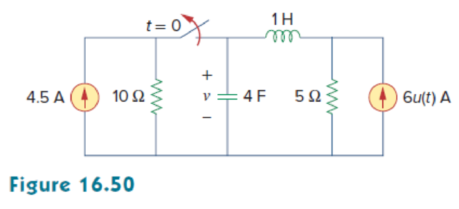
Find v (t) for t > 0 in the circuit in Fig. 16.50.
Expert Solution & Answer
Want to see the full answer?
Check out a sample textbook solution
Students have asked these similar questions
With the aid of suitable diagrams, describe the benefits that antenna arrays have over singleelement antennas, with their applications
Explain what is meant by an electric dipole antenna, sketch its radiation pattern, state itsdirectivity and describe its main applications
Estimate the length required for a half-waveelectric dipole antenna for transmitting/receiving EM waves at 800 MHz (this is in the UHFbandwidth of 470 to 860 MHz, used for UK TV transmissions).
Chapter 16 Solutions
EBK FUNDAMENTALS OF ELECTRIC CIRCUITS
Ch. 16.2 - Determine vo(t) in the circuit of Fig. 16.6,...Ch. 16.2 - Prob. 2PPCh. 16.2 - Prob. 3PPCh. 16.3 - For the circuit shown in Fig. 16.12 with the same...Ch. 16.3 - Prob. 5PPCh. 16.3 - The initial energy in the circuit of Fig. 16.17 is...Ch. 16.4 - Prob. 7PPCh. 16.4 - Prob. 8PPCh. 16.4 - Prob. 9PPCh. 16.5 - Obtain the state variable model for the circuit...
Ch. 16.5 - Prob. 11PPCh. 16.5 - Prob. 12PPCh. 16.6 - For what value of is the circuit in Fig. 16.29...Ch. 16.6 - Prob. 14PPCh. 16.6 - Prob. 15PPCh. 16.6 - Synthesize the function Vo(s)Vin=2ss2+6s+10 using...Ch. 16 - Prob. 1RQCh. 16 - The current through an RL series circuit with...Ch. 16 - Prob. 3RQCh. 16 - Prob. 4RQCh. 16 - Prob. 5RQCh. 16 - Prob. 6RQCh. 16 - Prob. 7RQCh. 16 - Prob. 8RQCh. 16 - Prob. 9RQCh. 16 - Prob. 10RQCh. 16 - The current in an RLC circuit is described by...Ch. 16 - The differential equation that describes the...Ch. 16 - Prob. 3PCh. 16 - If R = 20 , L = 0.6 H, what value of C will make...Ch. 16 - The responses of a series RLC circuit are vc(t) =...Ch. 16 - Prob. 6PCh. 16 - Prob. 7PCh. 16 - Prob. 8PCh. 16 - Prob. 9PCh. 16 - The step responses of a series RLC circuit are Vc...Ch. 16 - The step response of a parallel RLC circuit is v =...Ch. 16 - Prob. 12PCh. 16 - Prob. 13PCh. 16 - Prob. 14PCh. 16 - For the circuit in Fig. 16.38. calculate the value...Ch. 16 - The capacitor in the circuit of Fig. 16.39 is...Ch. 16 - If is(t) = 7.5e2t u(t) A in the circuit shown in...Ch. 16 - Find v(t), t 0 in the circuit of Fig. 16.41. Let...Ch. 16 - The switch in Fig. 16.42 moves from position A to...Ch. 16 - Find i(t) for t 0 in the circuit of Fig. 16.43.Ch. 16 - In the circuit of Fig. 16.44, the switch moves...Ch. 16 - Find the voltage across the capacitor as a...Ch. 16 - Obtain v (t) for t 0 in the circuit of Fig....Ch. 16 - The switch in the circuit of Fig. 16.47 has been...Ch. 16 - Calculate v(t) for t 0 in the circuit of Fig....Ch. 16 - Prob. 26PCh. 16 - Find v (t) for t 0 in the circuit in Fig. 16.50.Ch. 16 - For the circuit in Fig. 16.51, find v(t) for t 0.Ch. 16 - Prob. 29PCh. 16 - Find vo(t), for all t 0, in the circuit of Fig....Ch. 16 - Prob. 31PCh. 16 - For the network in Fig. 16.55, solve for i(t) for...Ch. 16 - Using Fig. 16.56, design a problem to help other...Ch. 16 - Prob. 34PCh. 16 - Prob. 35PCh. 16 - Prob. 36PCh. 16 - Prob. 37PCh. 16 - The switch in the circuit of Fig. 16.61 is moved...Ch. 16 - Prob. 39PCh. 16 - Prob. 40PCh. 16 - Prob. 41PCh. 16 - Prob. 42PCh. 16 - Prob. 43PCh. 16 - Prob. 44PCh. 16 - Find v(t) for t 0 in the circuit in Fig. 16.68.Ch. 16 - Prob. 46PCh. 16 - Determine io(t) in the network shown in Fig....Ch. 16 - Prob. 48PCh. 16 - Find i0(t) for t 0 in the circuit in Fig. 16.72....Ch. 16 - Prob. 50PCh. 16 - In the circuit of Fig. 16.74, find i(t) for t 0.Ch. 16 - Prob. 52PCh. 16 - In the circuit of Fig. 16.76, the switch has been...Ch. 16 - Prob. 54PCh. 16 - Prob. 55PCh. 16 - Calculate io(t) for t 0 in the network of Fig....Ch. 16 - Prob. 57PCh. 16 - Prob. 58PCh. 16 - Find vo(t) in the circuit of Fig. 16.82 if vx(0) =...Ch. 16 - Prob. 60PCh. 16 - Prob. 61PCh. 16 - Using Fig. 16.85, design a problem to help other...Ch. 16 - Consider the parallel RLC circuit of Fig. 16.86....Ch. 16 - The switch in Fig. 16.87 moves from position 1 to...Ch. 16 - For the RLC circuit shown in Fig. 16.88, find the...Ch. 16 - For the op amp circuit in Fig. 16.89, find v0(t)...Ch. 16 - Given the op amp circuit in Fig. 16.90, if v1(0+)...Ch. 16 - Prob. 68PCh. 16 - Prob. 69PCh. 16 - Using Fig. 16.93, design a problem to help other...Ch. 16 - Prob. 71PCh. 16 - The transfer function of a system is H(s)=s23s+1...Ch. 16 - Prob. 73PCh. 16 - Design a problem to help other students better...Ch. 16 - Prob. 75PCh. 16 - For the circuit in Fig. 16.95, find H(s) =...Ch. 16 - Obtain the transfer function H(s) = VoVs for the...Ch. 16 - Prob. 78PCh. 16 - For the circuit in Fig. 16.97, find: (a) I1/Vs (b)...Ch. 16 - Refer to the network in Fig. 16.98. Find the...Ch. 16 - Prob. 81PCh. 16 - Prob. 82PCh. 16 - Refer to the RL circuit in Fig. 16.101. Find: (a)...Ch. 16 - A parallel RL circuit has R = 4 and L = 1 H. The...Ch. 16 - Prob. 85PCh. 16 - Prob. 86PCh. 16 - Prob. 87PCh. 16 - Prob. 88PCh. 16 - Develop the state equations for the circuit shown...Ch. 16 - Prob. 90PCh. 16 - Prob. 91PCh. 16 - Prob. 92PCh. 16 - Prob. 93PCh. 16 - Prob. 94PCh. 16 - Prob. 95PCh. 16 - Prob. 96PCh. 16 - A system is formed by cascading two systems as...Ch. 16 - Determine whether the op amp circuit in Fig....Ch. 16 - It is desired realize the transfer function...Ch. 16 - Prob. 100PCh. 16 - Prob. 101PCh. 16 - Synthesize the transfer function...Ch. 16 - Prob. 103CPCh. 16 - Prob. 104CPCh. 16 - Prob. 105CP
Knowledge Booster


Learn more about
Need a deep-dive on the concept behind this application? Look no further. Learn more about this topic, electrical-engineering and related others by exploring similar questions and additional content below.Similar questions
- If the voltage waveform in Fig. 6.68 is applied to a 50-mH inductor, find the inductor current i(1). Assume i(0) = 0.arrow_forwardQ3/A 8-pole, 3-phase, 50 Hz induction motor, running at 725 r.p.m, rotor is star connected its resistance and reactance 0.25 and 1.5 ohm per phase, the emf between slip rings is 100, find the rotor current per phase, power factor, synchronous speed, slip and rotor frequencyarrow_forward440 v, 4-pole, 3-phase, 50 Hz, star stator connected induction motor, full load speed 1425 r.p.m, rotor impedance 0.5+4.55ohm and rotor/stator ratio 0.8 calculate 1) starting torque, (2) rotor current (3) the value of external resistance to add to give maximum starting torque (4) power factor at maximum torque.arrow_forward
- I would like to know the gear ratio and the tractive effort that a trolley must achieve with the following motor specifications: Voltage: 600 voltsSpeed: 1750 to 2300 RPMCurrent: 84 AmpsRated Power: 50-55 HP What percentage should be considered for gear efficiency, and what safe margin should be applied in these calculations? The constraints for the truck trolley are as follows:Maximum Speed: 50 MPHWeight of the Car Body: 46,000 lbs (the trolley weighs approximately 44,000 lbs)Diameter wheels: 86 inchesAdditionally, I would like to know how to plot a graph of tractive effort (in grams) versus speed (in MPH).arrow_forwardA scientist proposed building an EM wave as E= 6000 sin (300 x -5000t) j + 6000 sin (300 x -5000t)k andB= -0.25 sin (300 x -5000t) i + 0.25 sin (300 x -5000t) k. Explain why this is not possible and explain all the mistakes E= 6000 sin (300 x -wt) j . Find the value for w and find the magnetic field vector and the Poynting vector as afunction of x and t.arrow_forwardSolve this problem and show all of the workarrow_forward
- Solve this problem and show all of the workarrow_forward2. A system with unity feedback is shown below. The feed-forward transfer function is G(s), where 5 . G(S) = (+1) Sketch the root locus for the variations in the values of pi. (s+P1)s R(s) C(s) G(s)arrow_forward3. The following closed-loop systems in Fig. 1 and Fig. 2 operate with a damping ratio of 0.707 (=0.707). The system in Fig. 1 does not have a PI controller, while the one in Fig. 2 does. R(s): S Gain Plant R(s) + E(s) 1 C(s) K (s+1)(s+2)(s+10) Fig. 1: Closed-loop system without PI controller Compensator Plant R(s) + E(s) K(s+0.1) S 1 (s+1)(s+2)(s+10) C(s) Fig. 2: Closed-loop system with a practical PI controller a. Please use Matlab to find the intersection point between line and the root locus of the system in Fig. 1. Then find the K value and one complex closed-loop pole corresponding to the intersection point. Calculate the steady-state error. Show the Matlab code in your answer sheet. b. Please use Matlab to find the intersection point between § line and the root locus of the system in Fig. 2. Then find the K value and one complex closed-loop pole associated with the intersection point. Compare the complex closed-loop pole with the one you just found in task a. Are they very…arrow_forward
- 1. Please draw the root locus by hand for the following closed-loop system, where G(s) = s+6 = S-2 s+8 s-2' and H(s) = Find the range of K for stability using Method II in Examples 2 and 3 in Lecture 15. Input R(s) Output C(s) KG(s) H(s)arrow_forward9-1) Lathi & Ding, Prob. P.5.1-10 (a) A first-order-hold circuit can also be used to reconstruct a signal g(t) from its samples. The impulse response of this circuit is h(t) = A ( 2Ts 12 where Ts is the sampling interval. Consider a typical sampled signal ğ(t) and show that this circuit performs the linear interpolation. In other words, the filter output consists of sample tops connected by straight-line segments. Follow the procedure discussed in Sec. 5.1.2 (Fig. 5.6) for a typical signal g(t). (b) Determine the transfer function of this filter and its amplitude response, and compare it with the ideal filter required for signal reconstruction.arrow_forwardI have this rough circuit diagram of a 2 double end trolley light system with a 120 dcv power supply. I would like to know in what way is better to connect the interior lights along with the headlight and door light. Provide the circuit diagram and with its respect connection and the estimated total power rated for the lights. Where: Headlights (2) = #1 and #6Door lights (4) = #2, #4, #5, and #7Platform lights (2) = #3 and #8Interior lights are approximately 20 in quantity. Also, can you say if the components that are in series with the power supply are correct or does it need to be replaced with something else or if it is missing any components.arrow_forward
arrow_back_ios
SEE MORE QUESTIONS
arrow_forward_ios
Recommended textbooks for you
 Introductory Circuit Analysis (13th Edition)Electrical EngineeringISBN:9780133923605Author:Robert L. BoylestadPublisher:PEARSON
 Delmar's Standard Textbook Of ElectricityElectrical EngineeringISBN:9781337900348Author:Stephen L. HermanPublisher:Cengage Learning
 Programmable Logic ControllersElectrical EngineeringISBN:9780073373843Author:Frank D. PetruzellaPublisher:McGraw-Hill Education
 Fundamentals of Electric CircuitsElectrical EngineeringISBN:9780078028229Author:Charles K Alexander, Matthew SadikuPublisher:McGraw-Hill Education
 Electric Circuits. (11th Edition)Electrical EngineeringISBN:9780134746968Author:James W. Nilsson, Susan RiedelPublisher:PEARSON
 Engineering ElectromagneticsElectrical EngineeringISBN:9780078028151Author:Hayt, William H. (william Hart), Jr, BUCK, John A.Publisher:Mcgraw-hill Education,
Introductory Circuit Analysis (13th Edition)
Electrical Engineering
ISBN:9780133923605
Author:Robert L. Boylestad
Publisher:PEARSON
Delmar's Standard Textbook Of Electricity
Electrical Engineering
ISBN:9781337900348
Author:Stephen L. Herman
Publisher:Cengage Learning
Programmable Logic Controllers
Electrical Engineering
ISBN:9780073373843
Author:Frank D. Petruzella
Publisher:McGraw-Hill Education
Fundamentals of Electric Circuits
Electrical Engineering
ISBN:9780078028229
Author:Charles K Alexander, Matthew Sadiku
Publisher:McGraw-Hill Education
Electric Circuits. (11th Edition)
Electrical Engineering
ISBN:9780134746968
Author:James W. Nilsson, Susan Riedel
Publisher:PEARSON
Engineering Electromagnetics
Electrical Engineering
ISBN:9780078028151
Author:Hayt, William H. (william Hart), Jr, BUCK, John A.
Publisher:Mcgraw-hill Education,
Systems and Simulation - Lecture 3: Modelling of Mechanical systems; Author: bioMechatronics Lab;https://www.youtube.com/watch?v=fMcDdyoC9mA;License: Standard Youtube License