
Videos
Find vo(t), for all t > 0, in the circuit of Fig. 16.53.
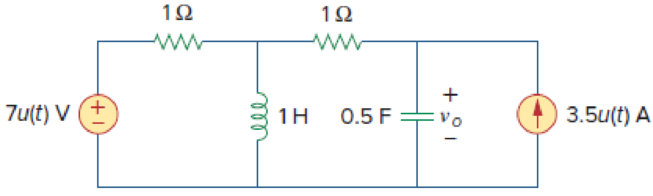
Figure 16.53
Find the expression of voltage
Answer to Problem 30P
The expression of voltage
Explanation of Solution
Given data:
Refer to Figure 16.53 in the textbook.
Formula used:
Write an expression to calculate the value of step input.
Write a general expression to calculate the impedance of a resistor in s-domain.
Here,
Write a general expression to calculate the impedance of an inductor in s-domain.
Here,
Write a general expression to calculate the impedance of a capacitor in s-domain.
Here,
Calculation:
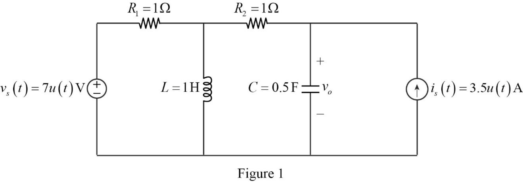
The given circuit is redrawn as shown in Figure 1.
For a DC circuit, at steady state condition at time
For time
The current source
The voltage source
When the value of current source is zero, it is open circuited and when the value of voltage source is zero it is short circuited.
Now, the Figure 1 is reduced as shown in Figure 2.
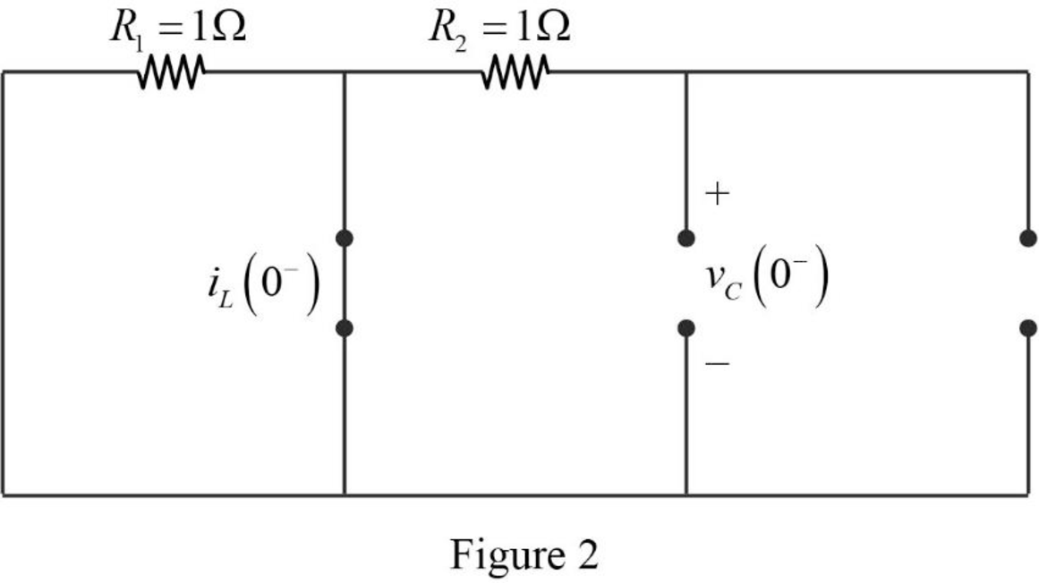
Refer to Figure 2, there is no current and voltage source placed in the circuit. Therefore, the value of current through the inductor and capacitor is equal to zero.
The current through inductor and voltage across capacitor is always continuous so that,
For time
Apply Laplace transform for
Apply Laplace transform for
Use equation (1) to find
Use equation (1) to find
Substitute
Substitute
Convert the Figure 1 into s-domain as shown in Figure 3.
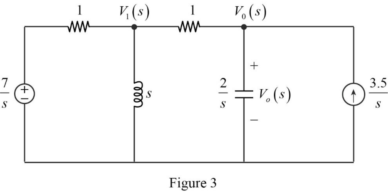
Apply nodal analysis at node
Apply nodal analysis at node
Simplify the above equation to find
Substitute
Simplify the above equation as follows:
Simplify the above equation to find
From equation (5), the characteristic equation of denominator is written as follows:
Write a general expression to calculate the roots of quadratic equation
Comparing the equation (6) with the equation
Substitute
Simplify the above equation to find
Substitute the roots of characteristic equation in equation (5) to find
Take partial fraction for above equation.
The equation (8) can also be written as follows:
Simplify the above equation as follows:
Substitute
Simplify the above equation to find
Substitute
Simplify the above equation to find
Substitute
Simplify the above equation to find
Substitute
Take inverse Laplace transform for above equation to find
Simplify the above equation to find
Conclusion:
Thus, the expression of voltage
Want to see more full solutions like this?
Chapter 16 Solutions
EBK FUNDAMENTALS OF ELECTRIC CIRCUITS


- 5. Find the Transfer Function of the following circuit. Prove that it’s a low pass filter, show all steps.arrow_forward2. Find the transfer function, show all steps.arrow_forwardI have this fsk function code: function [x]=fsk_encode(b,s,f0,f1,N,Fs,K) % b= bit sequence vector % s(1)= output level for 0 % s(2)= output level for 1 % N= length of bit sequence % Fs= Sampling frequency y=zeros(1,N*K); %Setup output vector %for each bit calculatee the rando samples for n=1:N for k=1:K t = (k - 1) / Fs; if(b(n)==0) y((n-1)*K+k)=cos(2*pi*f0*t); % pulse=0 else y((n-1)*K+k)=cos(2*pi*f1*t); % pulse=1 end end x=y; %set output end And this is another code that calls the function in order to get the power density spectrum: clc;clear; % EE 382 Communication Systems- Lab 8 % Plots the power spectrum of the ASK modulation % First specify some parameters N=256; % number of bits per realization M=100; % number of realizations in the ensemble T=0.001; % bit duration in seconds delf =2e+3; fc=10e+3; f0=fc-delf; f1=fc+delf; Fs=8*f1; % sampling frequency (this is needed to calibrate the frequency axis) K=(T/(1/Fs)); % Define arrays for bit sequences and sampled waveforms…arrow_forward
- Calculate the parameters in the figurearrow_forwardWrite the angle expression form of first null beam width FNBW) for 2/2 dipole. for 즐, 꽃 3arrow_forwardThe circuit is in the DC steady state, So all transients are passed. What are the values of 1 and V, under those conditions. P 24v + + √2 АЛАД 42 4F 3.H ww 22 eee + 203 Varrow_forward
- Find the value of Vc (t) for all I That is, the complete response including natural and forced responses.) АДДА 422 OV ДААД t = 0 3F + V(t) -arrow_forward1.0 Half-power point (left) 0.5 Minor lobes Main lobe maximum direction Main lobe Half-power point (right) Half-power beamwidth (HP) Beamwidth between first nulls (BWFN) *Which of the following Lobes of an antenna Pattern 180 out of Phase the main Lobe ? And where are the ch other gems ?arrow_forwardThe normalized radiation intensity of an antenna is represented by U(0) = cos² (0) cos² (30), w/sr Find the a. half-power beamwidth HPBW (in radians and degrees) b. first-null beamwidth FNBW (in radians and degrees)arrow_forward
 Introductory Circuit Analysis (13th Edition)Electrical EngineeringISBN:9780133923605Author:Robert L. BoylestadPublisher:PEARSON
 Delmar's Standard Textbook Of ElectricityElectrical EngineeringISBN:9781337900348Author:Stephen L. HermanPublisher:Cengage Learning
 Programmable Logic ControllersElectrical EngineeringISBN:9780073373843Author:Frank D. PetruzellaPublisher:McGraw-Hill Education
 Fundamentals of Electric CircuitsElectrical EngineeringISBN:9780078028229Author:Charles K Alexander, Matthew SadikuPublisher:McGraw-Hill Education
 Electric Circuits. (11th Edition)Electrical EngineeringISBN:9780134746968Author:James W. Nilsson, Susan RiedelPublisher:PEARSON
 Engineering ElectromagneticsElectrical EngineeringISBN:9780078028151Author:Hayt, William H. (william Hart), Jr, BUCK, John A.Publisher:Mcgraw-hill Education,