
Videos
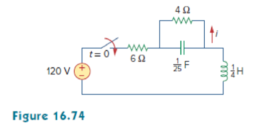
In the circuit of Fig. 16.74, find i(t) for t > 0.
Find the expression of current
Answer to Problem 51P
The expression of current
Explanation of Solution
Given data:
Refer to Figure 16.74 in the textbook.
Formula used:
Write a general expression to calculate the impedance of a resistor in s-domain.
Here,
Write a general expression to calculate the impedance of an inductor in s-domain.
Here,
Write a general expression to calculate the impedance of a capacitor in s-domain.
Here,
Calculation:
The given circuit is redrawn as shown in Figure 1.
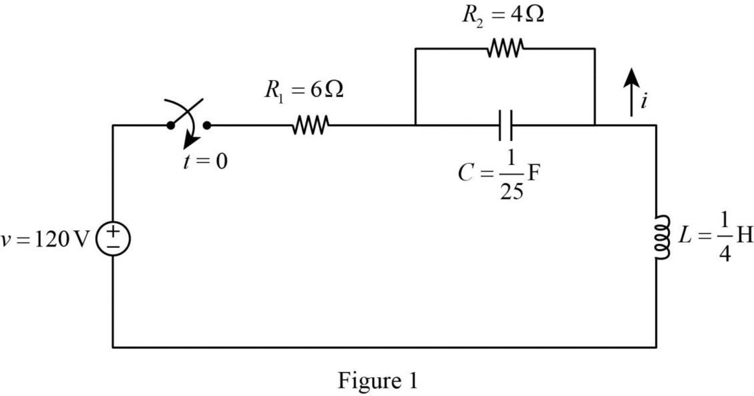
For a DC circuit, at steady state condition when time
Now, the Figure 1 is reduced as shown in Figure 2.
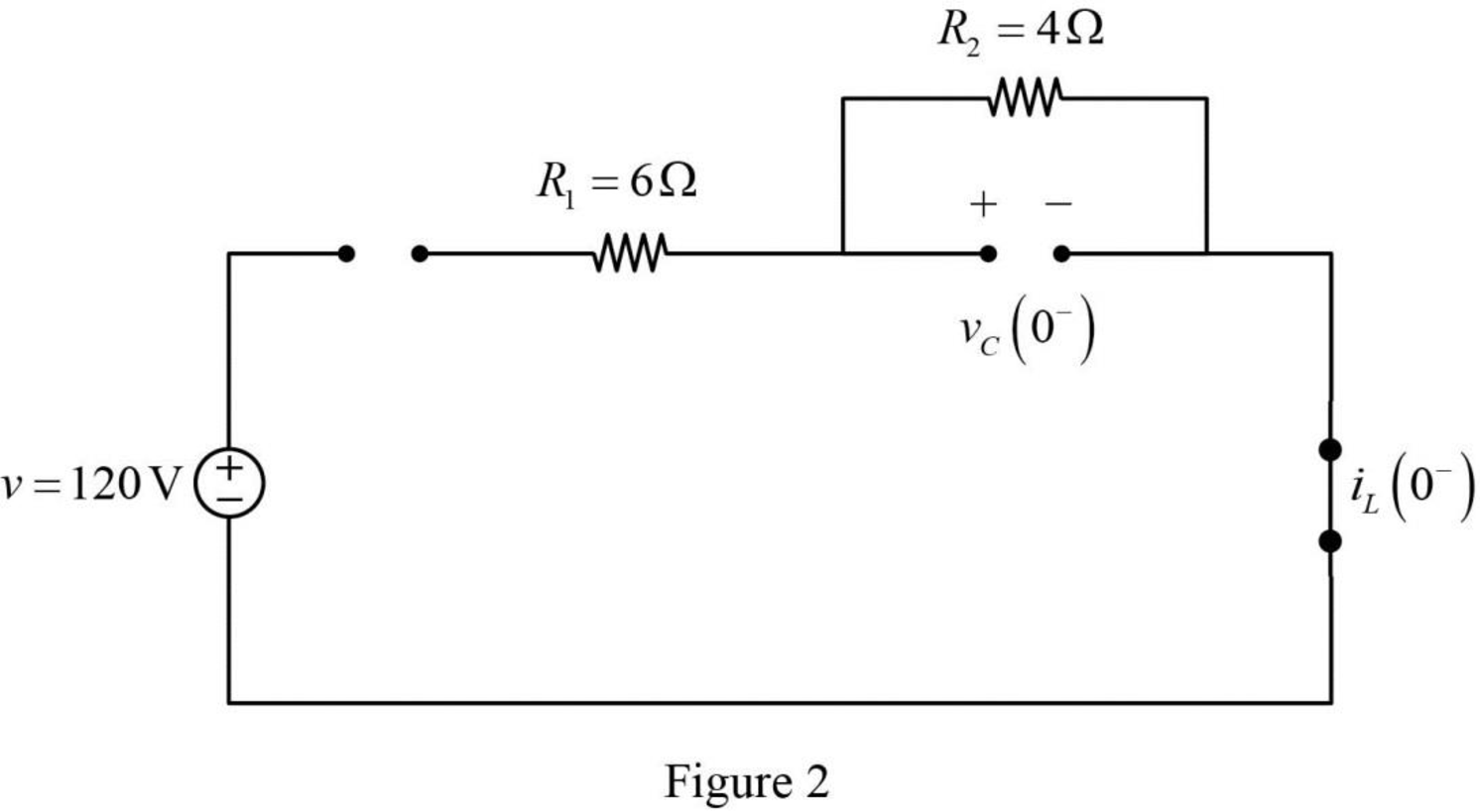
Refer to Figure 2, the switch is open and there is no source connected to the circuit. Therefore, the voltage across the capacitor and current through inductor are zero.
The current through inductor and voltage across capacitor is always continuous so that,
For time
Substitute
Substitute
Substitute
Substitute
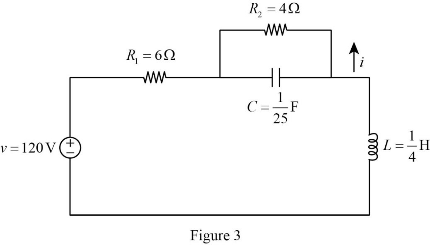
Refer to Figure 3, the circuit for
Apply Laplace transform for above to find
Convert the Figure 3 into s-domain.
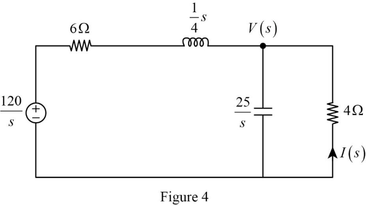
Apply nodal analysis at node
Simplify the above equation as follows:
Simplify the above equation as follows:
Simplify the above equation to find
From the above equation, the characteristic equation is
Write a general expression to calculate the roots of quadratic equation
Comparing equation (5) with the equation
Substitute
Simplify the above equation to find
Substitute the roots of characteristic equation in equation (4) to find
Take partial fraction for above equation.
The equation (7) can also be written as follows:
Simplify the above equation as follows:
Substitute
Simplify the above equation as follows:
Simplify the above equation to find
Substitute
Simplify the above equation to find
Substitute
Simplify the above equation to find
Substitute
Refer to Figure 3, the current through resistor
Substitute
Take inverse Laplace transform for above equation to find
Simplify the above equation to find
Conclusion:
Thus, the expression of current
Want to see more full solutions like this?
Chapter 16 Solutions
EBK FUNDAMENTALS OF ELECTRIC CIRCUITS


- i need helppp pleasearrow_forward1) (2pts) If you know you have a bad clock (lots of jitter) and you are not bandwidth constrained, you should: (Circle the correct answer) a) Set the roll off factor to zero b) Set the roll off factor to ½ c) Set the roll off factor to one 2) (2pts) Short answer: Why do we use M-ary modulation? 3) (4 pts) Short answer: The application engineer comes to your desk and says that the error rate is too high and must be reduced for the application to function correctly. The system is battery operated. What do you tell them is the trade- off?arrow_forwardi need helppp pleasearrow_forward
- 5) (20 pts) You are testing a system that has pulse shape shown below for Logic 1 and Logic 0. You are connecting the transmitter to an oscilloscope which is set up to display the resulting eye-diagram of the system. Sketch what you would expect to see on the oscilloscope for an ideal system (an ideal system is noiseless and jitter free) Logic 1 3 volts Time 0 Ть Logic 0 0 Ть Time -2 voltsarrow_forward4. (20 pts) You are given a channel with the following impulse response. Determine the set of equations that will be used to determine the coefficients of a Zero-Forcing Linear Equalizer. DO NOT SOLVE FOR THE COEFFICIENTS. Just show the set of equation that would be used to solved the coefficients. 0 m≤-31 -0.33 m = -2 .25 m = -1 h(mb) = 1 m = 0 -0.45 m = 1 0.5 m = 2 0 m≥3arrow_forwardI need help understanding part B. See attached photo.arrow_forward
- i need helppp pleasearrow_forward3) (30pts) An application requires a bit rate of 18.2 Kbps and an error rate of less than 104. The channel has a noise power spectral density of 10-8 W/Hz. The channel attenuates the power in the signal by 5 dB. The system uses binary PAM baseband digital communication system with the minimum required bandwidth and a roll-off factor of 0.319. a) (10 pts) What is the estimated minimum required signal power (Pt) at the transmitter?arrow_forwardi need helppp pleasearrow_forward
- i need helppp pleasearrow_forwardi need helppp pleasearrow_forward1a) (5pts) Suppose X is a Gaussian random variable with a mean of 2 and a variance of 9. What is the probability X is greater than 2. 1b) (5pts) Suppose X is a Gaussian random variable with a mean of 2 and a variance of 9. Using the Q-function, determine Prob{-4-2} Leave your answer in terms of the Q-function; do not evaluate it.arrow_forward
 Introductory Circuit Analysis (13th Edition)Electrical EngineeringISBN:9780133923605Author:Robert L. BoylestadPublisher:PEARSON
 Delmar's Standard Textbook Of ElectricityElectrical EngineeringISBN:9781337900348Author:Stephen L. HermanPublisher:Cengage Learning
 Programmable Logic ControllersElectrical EngineeringISBN:9780073373843Author:Frank D. PetruzellaPublisher:McGraw-Hill Education
 Fundamentals of Electric CircuitsElectrical EngineeringISBN:9780078028229Author:Charles K Alexander, Matthew SadikuPublisher:McGraw-Hill Education
 Electric Circuits. (11th Edition)Electrical EngineeringISBN:9780134746968Author:James W. Nilsson, Susan RiedelPublisher:PEARSON
 Engineering ElectromagneticsElectrical EngineeringISBN:9780078028151Author:Hayt, William H. (william Hart), Jr, BUCK, John A.Publisher:Mcgraw-hill Education,