
Principles of Geotechnical Engineering (MindTap Course List)
9th Edition
ISBN: 9781305970939
Author: Braja M. Das, Khaled Sobhan
Publisher: Cengage Learning
expand_more
expand_more
format_list_bulleted
Concept explainers
Videos
Textbook Question
Chapter 16, Problem 16.4P
Redo Problem 16.1 with the following: γ = 16.5 kN/m3, cu = 41 kN/m3,
16.1 A continuous footing is shown in Figure 16.17. Using Terzaghi’s bearing capacity factors, determine the gross allowable load per unit area (qall) that the footing can carry. Assume general shear failure. Given: γ = 19 kN/m3, c′ = 31kN/m2,
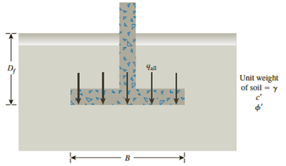
Figure 16.17
Expert Solution & Answer
Want to see the full answer?
Check out a sample textbook solution
Students have asked these similar questions
A hoist trolley is subjected to the three forces shown. Knowing that α = 40°, determine (a) the required magnitude of the force P if
the resultant of the three forces is to be vertical, (b) the corresponding magnißide of the resultant.
α
724lb
last 3 student's ID# lb
α
last 2 student's ID#+100 lb
124lb
P
Five wood boards are bolted together to
form the built-up beam shown in the
figure. The beam is subjected to a
shear force of V = 13 kips. Each bolt
has a shear strength of Vbolt = 6 kips.
[h₁ =4.25 in., t₁ = 0.5 in., h₂ = 6 in., t₂ =
1 in.]
hi
+
hi/2
h:/2
h: 2
h
+
h/2
Determine the moment of inertia of the
section.
Determine the maximum allowable
spacing of the bolts.
Determine the shear flow in the section
connected by fasteners.
A vessel has a diameter of 1m and 2m high is moving downward with a positive acceleration of 3m/s2. The pressure at the bottom of the liquid is 9.534kPa, determine the mass of the liquid.
Chapter 16 Solutions
Principles of Geotechnical Engineering (MindTap Course List)
Ch. 16 - A continuous footing is shown in Figure 16.17....Ch. 16 - Refer to Problem 16.1. If a square footing with...Ch. 16 - Redo Problem 16.1 with the following: = 115...Ch. 16 - Redo Problem 16.1 with the following: = 16.5...Ch. 16 - Redo Problem 16.1 using the modified general...Ch. 16 - Redo Problem 16.2 using the modified general...Ch. 16 - Redo Problem 16.3 using the modified general...Ch. 16 - Redo Problem 16.4 using the modified general...Ch. 16 - Prob. 16.9PCh. 16 - If the water table in Problem 16.9 drops down to...
Ch. 16 - Prob. 16.11PCh. 16 - A square footing is subjected to an inclined load...Ch. 16 - A square footing (B B) must carry a gross...Ch. 16 - Redo Problem 16.13 with the following data: gross...Ch. 16 - Refer to Problem 16.13. Design the size of the...Ch. 16 - Prob. 16.16PCh. 16 - Prob. 16.17PCh. 16 - Refer to the footing in Problem 16.16. Determine...Ch. 16 - Figure 16.21 shows a continuous foundation with a...Ch. 16 - The following table shows the boring log at a site...
Knowledge Booster


Learn more about
Need a deep-dive on the concept behind this application? Look no further. Learn more about this topic, civil-engineering and related others by exploring similar questions and additional content below.Similar questions
- You are the engineer asked to design a rapid sand filtration system for a small water treatment plant. It has the following characteristics: Hydraulic loading rate = 6 m/h Total volumetric flow rate of the plant = 3 MGD Effective filtration rate = 5.8 m/h Production efficiency = 97% Complete (filtration, rinsing, and backwashing) filter cycle duration = 48 h What is the area of your square filtration system? What are the surface dimensions of the filter? What volume of water is needed for backwashing plus rinsing the filter in each rinsing cycle?arrow_forwardFive wood boards are bolted together to form the built-up beam shown in the figure. The beam is subjected to a shear force of V = 14 kips. Each bolt has a shear strength of V bolt = 6 kips. [h₁ = 4 in., t₁ = 0.75 in., h₂ = 6.5 in., t₂ = 1.25 in.] h/2 + hi/2 h:/2 h: 2 hi + hiz Determine the moment of inertia of the section. Calculate the shear force in each bolt. Calculate the shear stress in the bolts.arrow_forwardA box beam is fabricated from two plywood webs that are secured to lumber boards at its top and bottom flanges. The beam supports a concentrated load of P = 4100 lb at the center of a 13-ft span. Bolts (3/8-in. diameter) connect the plywood webs and the lumber flanges at a spacing of s = 9 in. along the span. Supports A and C can be idealized as a pin and a roller, respectively. [w = 4.5 in., b = 0.25 in., t = 5 in., h = 17 in.] B Determine the maximum horizontal shear stress in the plywood webs. Determine the average shear stress in the bolts. Determine the maximum bending stress in the lumber flanges.arrow_forward
- A cantilever flexural member is fabricated by bolting two identical C- section steel shapes back to back as shown in the figure. The beam has a span of L = 1300 mm and supports a concentrated load of P = 800 N. The cross-sectional dimensions of the built- up shape are shown in the figure. Assume the section has a constant thickness of t = 2.5 mm. Bolts of 3.5 mm diameter are installed at intervals of s = 65 mm.[b = 100 mm, a = 25 mm] b T Determine the shear flow in the sections connected by the fasteners. Calculate the shear force in each bolt. Calculate the shear stress in the bolts.arrow_forwardFive wood boards are bolted together to form the built-up beam shown in the figure. The beam is subjected to a shear force of V = 14 kips. Each bolt has a shear strength of V bolt = 6 kips. [h₁4 in., t₁ = 0.75 in., h₂ = 6.5 in., t₂ = 1.25 in.] hi/2 h/2 h2 h:/2 hi/2 + h2 Determine the moment of inertia of the section. Determine the shear flow in the section connected by fasteners. Determine the maximum allowable spacing of the bolts.arrow_forwardTwo built-up beams shown in the figure below have the same dimensions and are connected by the same types of nails with the same spacing. Which beam could carry more shear force if the controlling factor is the shear flow in the fasteners? Nails Beam (1) Z Beam (2) Beam (2) Beam (1) Both are the same Cannot answer without knowing the shear diagram Cannot answer without knowing the modulus of rigidity Nailsarrow_forward
- Two built-up beams shown in the figure below have the same dimensions and are connected by the same types of nails with the same spacing. Which beam could carry more shear force if the controlling factor is the shear flow in the fasteners? Nails Beam (1) Beam (2) Cannot answer without knowing the shear diagram Beam (1) Cannot answer without knowing the modulus of Nailsarrow_forward8-51. Determine the horizontal displacement at C. Take E = 29(10³) ksi, I = 150 in for each member. Use the method of virtual work. 8ft 10 ft Barrow_forward5. Problem 8-46 on Page 374. 8-46. The L-shaped frame is made from two fixed-connected segments. Determine the vertical displacement of the end C. Use the method of virtual work. El is constant. -9 ft- 2 k/ft 12 ftarrow_forward
- HOMEWORK (1) For the plan and section of the wall shown below, calculate the following: - 1. the length of footing excavation 2, the length of bricks work under D.P.C for each step by using: a) Centre line method b) Long wall-short wall method عرف الحق Im D.P.C 1.00 m Section 0.24 m 0.36 m 0.48 m 15 m r N 8 m 5 m Plan Farrow_forwardfollowing: 1. the length of footing excavation 2. the length of bricks work under D.P.C for each step by using: a) Centre line method b) Long wall-short wall method D.P.C 1.00 m 0.24 m 0.36 m y0.48 m 15 m Section. N A k W 8 m 5 m زف الحو 不 Z Plan ate the Larrow_forwardPage 3 3.5) Using the Method of Components, determine the magnitude, the direction, and the sense of the resultant for the coplanar concurrent force system shown below. Y 76 lbs 10 kips 4 3 0 Y 12 kips 5 12 > x 60 lbsarrow_forward
arrow_back_ios
SEE MORE QUESTIONS
arrow_forward_ios
Recommended textbooks for you
 Principles of Foundation Engineering (MindTap Cou...Civil EngineeringISBN:9781337705028Author:Braja M. Das, Nagaratnam SivakuganPublisher:Cengage Learning
 Fundamentals of Geotechnical Engineering (MindTap...Civil EngineeringISBN:9781305635180Author:Braja M. Das, Nagaratnam SivakuganPublisher:Cengage Learning
 Principles of Geotechnical Engineering (MindTap C...Civil EngineeringISBN:9781305970939Author:Braja M. Das, Khaled SobhanPublisher:Cengage Learning
 Principles of Foundation Engineering (MindTap Cou...Civil EngineeringISBN:9781305081550Author:Braja M. DasPublisher:Cengage Learning
Principles of Foundation Engineering (MindTap Cou...
Civil Engineering
ISBN:9781337705028
Author:Braja M. Das, Nagaratnam Sivakugan
Publisher:Cengage Learning
Fundamentals of Geotechnical Engineering (MindTap...
Civil Engineering
ISBN:9781305635180
Author:Braja M. Das, Nagaratnam Sivakugan
Publisher:Cengage Learning
Principles of Geotechnical Engineering (MindTap C...
Civil Engineering
ISBN:9781305970939
Author:Braja M. Das, Khaled Sobhan
Publisher:Cengage Learning
Principles of Foundation Engineering (MindTap Cou...
Civil Engineering
ISBN:9781305081550
Author:Braja M. Das
Publisher:Cengage Learning
CE 414 Lecture 02: LRFD Load Combinations (2021.01.22); Author: Gregory Michaelson;https://www.youtube.com/watch?v=6npEyQ-2T5w;License: Standard Youtube License