Concept explainers
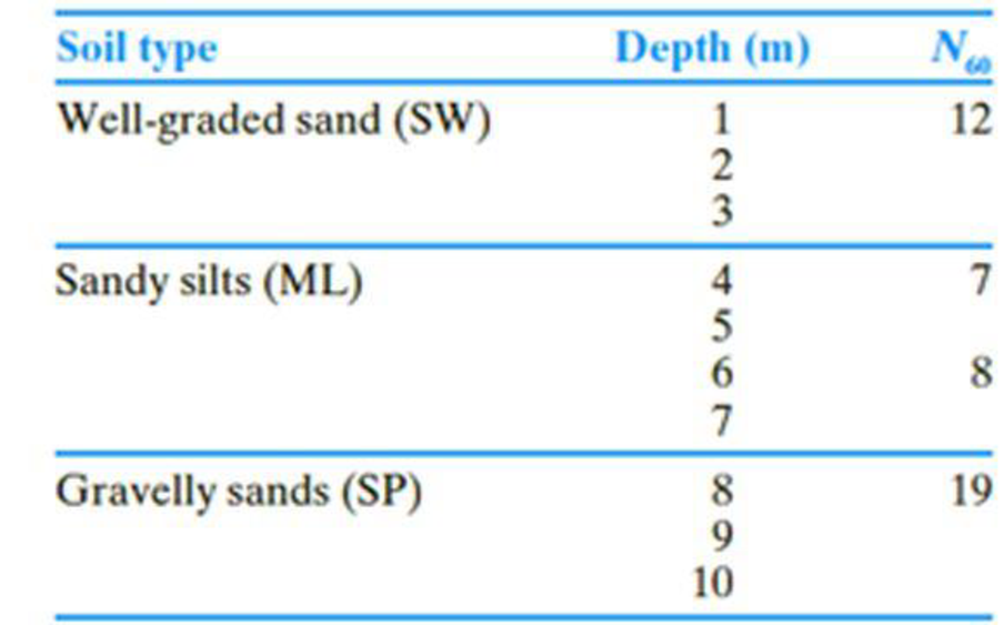
The following table shows the boring log at a site where a multi-story shopping center would be constructed. Soil classification and the standard penetration number, N60, are provided in the boring log. All columns of the building are supported by square footings which must be placed at a depth of 1.5 m. Additionally, the settlement (elastic) of each footing must be restricted to 20 mm. Since the column loads at different location can vary, a design chart is helpful for quick estimation of footing size required to support a given load.
- a. Prepare a chart by plotting the variation of maximum allowable column loads with footing sizes, B = 1 m, 1.5 m, 2 m, and 3 m. Use a factor of safety of 3.
- b. If the gross column load from the structure is 250 kN, how would you use this chart to select a footing size?
- c. What would be the design footing size for the column in Part (b) if you use Terzaghi’s bearing capacity equation? For the well graded sand, assume that ϕ′ = 33°. Use Fs = 3.
- d. Compare and discuss the differences in footing sizes obtained in Parts b and c.

(a)
Plot the variation of maximum allowable column loads with size of footings to prepare a chart.
Explanation of Solution
Given information:
The location of depth of footing
The given size of the footing B is 1 m, 1.5 m, 2 m, and 3 m.
The settlement of each footing
The given factor of safety
Calculation:
For B value is 1 m:
Determine the depth factor using the relation.
Substitute 1.5 m for
The
The field standard penetration number
Determine the depth of foundation for the field standard penetration number gets averaged.
Substitute 1.5 m for
Determine the averaged
Here,
Substitute 12 for
Determine the net allowable bearing capacity of the soil
Substitute 10 for
Determine the maximum allowable column load
Substitute
For B value is 1.5 m:
Determine the depth factor using the relation.
Substitute 1.5 m for
The field standard penetration number
Determine the depth of foundation for the field standard penetration number gets averaged.
Substitute 1.5 m for
Determine the averaged
Here,
Substitute 7 for
Determine the net allowable bearing capacity of the soil
Substitute 8 for
Determine the maximum allowable column load
Substitute
For B value is 2 m:
Determine the depth factor using the relation.
Substitute 1.5 m for
The field standard penetration number
Determine the depth of foundation for the field standard penetration number gets averaged.
Substitute 1.5 m for
Determine the averaged
Substitute 12 for
Determine the net allowable bearing capacity of the soil
Substitute 9 for
Determine the maximum allowable column load
Substitute
For B value is 3 m:
Determine the depth factor using the relation.
Substitute 1.5 m for
The field standard penetration number
Determine the depth of foundation for the field standard penetration number gets averaged.
Substitute 1.5 m for
Determine the averaged
Here,
Substitute 12 for
Determine the net allowable bearing capacity of the soil
Substitute 12 for
Determine the maximum allowable column load
Substitute
Summarize the calculated values as in Table (1).
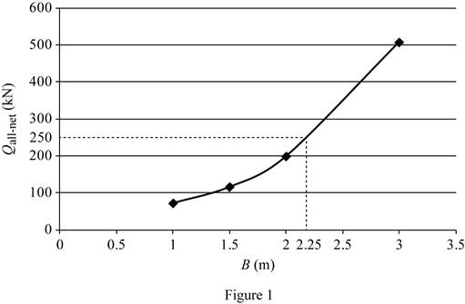
| Width B (m) | Column load (kN) |
| 1 | 71 |
| 1.5 | 115 |
| 2 | 198 |
| 3 | 507.5 |
Plot the graph between the size of the footing and the column load as in Figure (1).

(b)
Find the footing size for the given gross column load of 250 kN.
Answer to Problem 16.1CTP
The footing size for the given gross column load of 250 kN is
Explanation of Solution
Given information:
The location of depth of footing
The given size of the footing B is 1 m, 1.5 m, 2 m, and 3 m.
The settlement of each footing
The given factor of safety
Calculation:
Refer Figure (1).
The size of the footing is 2.25 m for the gross column load of 250 kN.
Therefore, the footing size for the given gross column load of 250 kN is
(c)
Find the design column load for the footing size of 2.25 m using the Terzaghi’s bearing capacity equation.
Answer to Problem 16.1CTP
The design column load for the footing size of 2.25 m using the Terzaghi’s bearing capacity equation is
Explanation of Solution
Given information:
The value of cohesion
The soil friction angle
The location of depth of footing base
The width of the footing B is 2.25 m.
The given factor of safety
Calculation:
Determine the net ultimate bearing capacity of the soil
Here,
Take the unit weight of the soil
Refer Table 16.1, “Terzaghi’s bearing-capacity factors–
Take the
Substitute
Determine the net allowable bearing capacity
Substitute
Therefore, the design column load for the footing size of 2.25 m using the Terzaghi’s bearing capacity equation is
(d)
Compare and discuss the differences in footing sizes obtained in parts (b) and (c).
Explanation of Solution
Given information:
The soil friction angle
The location of depth of footing base
The width of the footing B is 2.25 m.
The given factor of safety
Calculation:
The net allowable column load obtained by using Terzaghi’s bearing capacity equation (2,173 kN) is significantly higher than the method based on the
Want to see more full solutions like this?
Chapter 16 Solutions
Bundle: Principles Of Geotechnical Engineering, Loose-leaf Version, 9th + Mindtap Engineering, 2 Terms (12 Months) Printed Access Card
- Determine the internal normal force, shear force, and moments at points E and D of the compound beam.arrow_forward6. Draw the shear and moment diagrams for the beam. 10 kN 10 kN/m 1 m 2 m. Aarrow_forward3. Identify and label the key components that make up the low-slope roofing system in the diagram below. (5 points)arrow_forward
- ASSIGNMENT. 1. The following figure is a billboard sketch, design the members. Hint, the billboard is usually designed against wind loads and its own self weight. For the dimensions, you can visit existing billboards to see usual dimensions. 3D Viewarrow_forwardIn order to solve the frame given below with the Force Method, remove restraints from joints A and G and draw only the bending moment diagrams Mo, M₁, M2 and M3 for this case. (25 Pts.) Note: Only bending moment diagrams that are used for the solution are required. There is no need to do any further calculations. 4 kN B I E D 2 kN/m H 3 m 3 m 4 m + 2 m 4marrow_forwardplease show complete solution with formulaarrow_forward
- please show complete solution, thank youarrow_forwardplease show complete solution, step by step, thanksarrow_forward1. What is the weight of each block shown below in pounds? A) 2’x2’x10’ Steel Bar w=490lb/ft^3 B) 5’x4’x3’ Concrete Block w=150lb/ft^3 A) 3’x10’x2’ Wood block w=50lb/ft^3 2.The 6” thick, 20’x25’ concrete slab weights 150lbs/ft^3 and has an area load of 50lbs/ft^2 (psf). What is the total load of the floor?arrow_forward
- Lab Assignment #2 Loads: UDL and Concentrated Name: TA 1. Use the provided beam models to solve for the equivalent concentrated load of each beam configuration. Draw the loading conditions showing the equivalent concentrated load(s). a) w = 30lbs/ft 6ft 6ft c) w = 50lbs/ft 12ft w = 70lbs/ft b) 4ft w = 20lbs/ft w = 40lbs/ft d) 9ft 2. Find the equivalent concentrated load(s) for the bags of cement stacked on the dock as shown here. Each bag weighs 100 lbs and is 12 inches long. Draw the loading conditions for each showing the equivalent concentrated load(s). 1 bag = 100lbs L= 12 ft L= 6ft L= 8ftarrow_forwardplease show the complete solution, step by step process, thanksarrow_forwardThe rectangular gate shown in figure rotates about an axis through N. If a=3.3 ft,b=1.3 ft, d=2 ft, and the width perpendicular to the plane of the figure is 3 ft, what torque(applied to the shaft through N) is required to hold the gate closed?arrow_forward
 Principles of Geotechnical Engineering (MindTap C...Civil EngineeringISBN:9781305970939Author:Braja M. Das, Khaled SobhanPublisher:Cengage Learning
 Principles of Foundation Engineering (MindTap Cou...Civil EngineeringISBN:9781337705028Author:Braja M. Das, Nagaratnam SivakuganPublisher:Cengage Learning
 Fundamentals of Geotechnical Engineering (MindTap...Civil EngineeringISBN:9781305635180Author:Braja M. Das, Nagaratnam SivakuganPublisher:Cengage Learning
 Principles of Foundation Engineering (MindTap Cou...Civil EngineeringISBN:9781305081550Author:Braja M. DasPublisher:Cengage Learning
 Construction Materials, Methods and Techniques (M...Civil EngineeringISBN:9781305086272Author:William P. Spence, Eva KultermannPublisher:Cengage Learning


