![MindTap Engineering for Das/Sobhan's Principles of Geotechnical Engineering, SI Edition, 9th Edition, [Instant Access], 2 terms (12 months)](https://s3.amazonaws.com/compass-isbn-assets/textbook_empty_images/large_textbook_empty.svg)
Concept explainers
Videos
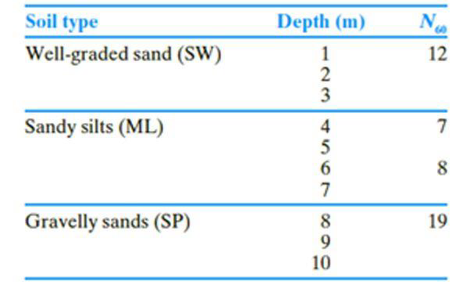
The following table shows the boring log at a site where a multi-story shopping center would be constructed. Soil classification and the standard penetration number, N60, are provided in the boring log. All columns of the building are supported by square footings which must be placed at a depth of 1.5 m. Additionally, the settlement (elastic) of each footing must be restricted to 20 mm. Since the column loads at different location can vary, a design chart is helpful for quick estimation of footing size required to support a given load.
- a. Prepare a chart by plotting the variation of maximum allowable column loads with footing sizes, B = 1 m, 1.5 m, 2 m, and 3 m. Use a factor of safety of 3.
- b. If the gross column load from the structure is 250 kN, how would you use this chart to select a footing size?
- c. What would be the design footing size for the column in Part (b) if you use Terzaghi’s bearing capacity equation? For the well graded sand, assume that ϕ′ = 33°. Use Fs = 3.
- d. Compare and discuss the differences in footing sizes obtained in Parts b and c.
(a)
Plot the variation of maximum allowable column loads with size of footings to prepare a chart.
Explanation of Solution
Given information:
The location of depth of footing
The given size of the footing B is 1 m, 1.5 m, 2 m, and 3 m.
The settlement of each footing
The given factor of safety
Calculation:
For B value is 1 m:
Determine the depth factor using the relation.
Substitute 1.5 m for
The
The field standard penetration number
Determine the depth of foundation for the field standard penetration number gets averaged.
Substitute 1.5 m for
Determine the averaged
Here,
Substitute 12 for
Determine the net allowable bearing capacity of the soil
Substitute 10 for
Determine the maximum allowable column load
Substitute
For B value is 1.5 m:
Determine the depth factor using the relation.
Substitute 1.5 m for
The field standard penetration number
Determine the depth of foundation for the field standard penetration number gets averaged.
Substitute 1.5 m for
Determine the averaged
Here,
Substitute 7 for
Determine the net allowable bearing capacity of the soil
Substitute 8 for
Determine the maximum allowable column load
Substitute
For B value is 2 m:
Determine the depth factor using the relation.
Substitute 1.5 m for
The field standard penetration number
Determine the depth of foundation for the field standard penetration number gets averaged.
Substitute 1.5 m for
Determine the averaged
Substitute 12 for
Determine the net allowable bearing capacity of the soil
Substitute 9 for
Determine the maximum allowable column load
Substitute
For B value is 3 m:
Determine the depth factor using the relation.
Substitute 1.5 m for
The field standard penetration number
Determine the depth of foundation for the field standard penetration number gets averaged.
Substitute 1.5 m for
Determine the averaged
Here,
Substitute 12 for
Determine the net allowable bearing capacity of the soil
Substitute 12 for
Determine the maximum allowable column load
Substitute
Summarize the calculated values as in Table (1).
| Width B (m) | Column load (kN) |
| 1 | 71 |
| 1.5 | 115 |
| 2 | 198 |
| 3 | 507.5 |
Plot the graph between the size of the footing and the column load as in Figure (1).
![MindTap Engineering for Das/Sobhan's Principles of Geotechnical Engineering, SI Edition, 9th Edition, [Instant Access], 2 terms (12 months), Chapter 16, Problem 16.1CTP](https://content.bartleby.com/tbms-images/9781305970939/Chapter-16/images/70939-16-16.1ctp_image001.jpg)
(b)
Find the footing size for the given gross column load of 250 kN.
Answer to Problem 16.1CTP
The footing size for the given gross column load of 250 kN is
Explanation of Solution
Given information:
The location of depth of footing
The given size of the footing B is 1 m, 1.5 m, 2 m, and 3 m.
The settlement of each footing
The given factor of safety
Calculation:
Refer Figure (1).
The size of the footing is 2.25 m for the gross column load of 250 kN.
Therefore, the footing size for the given gross column load of 250 kN is
(c)
Find the design column load for the footing size of 2.25 m using the Terzaghi’s bearing capacity equation.
Answer to Problem 16.1CTP
The design column load for the footing size of 2.25 m using the Terzaghi’s bearing capacity equation is
Explanation of Solution
Given information:
The value of cohesion
The soil friction angle
The location of depth of footing base
The width of the footing B is 2.25 m.
The given factor of safety
Calculation:
Determine the net ultimate bearing capacity of the soil
Here,
Take the unit weight of the soil
Refer Table 16.1, “Terzaghi’s bearing-capacity factors–
Take the
Substitute
Determine the net allowable bearing capacity
Substitute
Therefore, the design column load for the footing size of 2.25 m using the Terzaghi’s bearing capacity equation is
(d)
Compare and discuss the differences in footing sizes obtained in parts (b) and (c).
Explanation of Solution
Given information:
The soil friction angle
The location of depth of footing base
The width of the footing B is 2.25 m.
The given factor of safety
Calculation:
The net allowable column load obtained by using Terzaghi’s bearing capacity equation (2,173 kN) is significantly higher than the method based on the
Want to see more full solutions like this?
Chapter 16 Solutions
MindTap Engineering for Das/Sobhan's Principles of Geotechnical Engineering, SI Edition, 9th Edition, [Instant Access], 2 terms (12 months)


- A gravity retaining wall is shown in the figure below. Calculate the factor of safety with respect to overturning and sliding, given the following data: Wall dimensions: H = 6 m, x₁ = 0.6 m, x2 = 2 m, x3 = 2m, x4 0.5 m, x5 = 0.75 m, x6 = 0.8 m, D= 1.5 m Soil properties: 71 = 14 kN/m³, ₁ = 32°, 72 = 18 kN/m³, 2=22°, c₂ = 40 kN/m² Y₁ c₁ = 0 H Φί x5 x6 Use the Rankine active earth pressure in your calculation. Use Yconcrete = 23.08 kN/m³. Also, use k₁ = k₂ = 2/3 and Pp = 0 in the equation FS (sliding) (ΣV) tan(k102) + Bk2c2 + Pp Pa cos a (Enter your answers to three significant figures.) FS (overturning) FS (sliding) =arrow_forwardFor the cantilever retaining wall shown in the figure below, let the following data be given: Wall dimensions: H = 8 m, x1 = 0.4 m, x2 = 0.6 m, x3 = 1.5 m, x4 3.5 m, x5 = 0.96 m, D= 1.75 m, a = 10° Soil properties: 71 = 14.8 kN/m³, ₁ = 32°, Y₂ = 1 2 = 28°, c = 30 kN/m² 17.6 kN/m³, The value of Ka is 0.3210. For 2 = 28°: N = 25.80; N₁ = 14.72; N₁ = 16.72. c=0 H Χς Calculate the factor of safety with respect to overturning, sliding, and bearing capacity. Use Yconcrete = 21.58 kN/m³. Also, use k₁ = k₂ = 2/3 and P = 0 in the equation FS (sliding) (ΣV) tan(k₁₂) + Bk2C + Pp Pa cosa (Enter your answers to three significant figures.) FS (overturning) FS (sliding) FS (bearing) =arrow_forwardQuestion 2 The following strains are obtained by a 0-60-120 strain rosette: ε0 = 300 x 10-6, 60 = 200 x 10-6 and 120= 150 x 10-6. i. Determine strains Ex, Ey and Yxy ii. Determine the strains for 0 = 40° iii. Calculate principal strains, maximum shear strain and the orientation of principal strains iv. Determine normal stresses (σx, σy) and shear stress (Txy), if E = 200kPa and v = 0.25. (Hint: You may use stress-strain relationship for plane strain, summarised in matric format as follows: E σχ бу 1-v v 0 Ex = v 1-v 0 Ey txy. (1+v)(1 − 2v) 0 0 0.5 varrow_forward
- A gravity retaining wall is shown in the figure below. Calculate the factor of safety with respect to overturning and sliding, given the following data: Wall dimensions: H = 6 m, x1 = 0.6 m, x2 = 2 m, x3 = 2m, x4 0.5 m, x5 = 0.75 m, x6 = 0.8 m, D= 1.5 m Soil properties: 71 = 15.5 kN/m³, ₁ = 32°, Y2 = 18 kN/m³, 2=22°, c₂ = 40 kN/m² H x6 X2 TXT X3 Use Coulomb's active earth pressure in your calculation and let ' = 2/3 01. Use Yconcrete = 23.58 kN/m³. Also, use k₁ = k₂ = 2/3 and P = 0 in equation FS (sliding) (ΣV) tan(k₁₂2) + Bk2c + Pp Pa cos a For 1 = 32°, a = 0°, B = 71.57°, Ka = 0.45, 8' = 21.33°. (Enter your answers to three significant figures.) FS (overturning) FS (sliding) =arrow_forwardFor the cantilever retaining wall shown in the figure below, let the following data be given: Wall dimensions: H = 6.5 m, x1 = 0.3 m, x2 = 0.6 m, x3 = 0.8 m, x4 2 m, x5 = 0.8 m, D= 1.5 m, a = 0° Soil properties: 71 = 17.08 kN/m³, ₁ = 36°, Y2 = 19.65 kN/m³, 2 = 15°, c₂ = 30 kN/m² For 2=15°: N = 10.98; N₁ = 3.94; N₁ = 2.65. x2 .. c₁ = 0 Φί H x5 Calculate the factor of safety with respect to overturning, sliding, and bearing capacity. Use Yconcrete = 24.58 kN/m³. Also, use k₁ = k2 = 2/3 and P₂ = 0 in equation (EV) tan(k102) + Bk2c₂ + Pp FS (sliding) Pa cos a (Enter your answers to three significant figures.) FS (overturning) FS (sliding) FS (bearing) = = =arrow_forwardA) # of Disinfection Clearwells: 3 B) Clearwell Operation Style: Parallel (to provide contact time for disinfection using free chlorine (derived from a hypochlorite solution generated onsite). C) The facility's existing system to generate hypochlorite onsite has reached the end of its useful life, and the current operating capacity is insufficient to generate the required mass flow of hypochlorite to accommodate the future capacity of 34.5 MGD. Assume the facility plans to stop generating hypochlorite onsite and will instead purchase a bulk solution of sodium hypochlorite D) Sodium hypochlorite (NaOCI) concentration: 6.25% NaOCI by mass E) Bulk Density: 1,100 kg/m^3 F) Clearwell T10/DT Ratio: (CW1 0.43). (CW2 = 0.51), (CW3 = 0.58) DT is the theoretical mean hydraulic retention time (V/Q) G) pH: 7.0 H) Design Temperature: 15°C 1) 50% of Chlorine is lost in each clearwell J) If the concentration going into the clearwell is C, then you can assume that the concentration leaving the…arrow_forward
- Please explain step by step, and show formulaarrow_forwardNote: Please deliver a clear, step-by-step simplified handwritten solution (without any explanations) that is entirely manually produced without AI assistance. I expect an expert-level answer, and I will evaluate and rate it based on the quality and accuracy of the work, using the provided image for additional reference. Ensure every detail is thoroughly checked for correctness before submission.arrow_forwardPlease don't explain it. But draw it out for me kindly. And appreciate your time!. All the info is in the images. Thanks!.arrow_forward
- Design a simply supported one-way pavement slab for a factored applied moment, Mu = 10 ft-kip. Use f c’ = 5,000 psi and f y = 60,000 psi. The slab is in permanent contact with soil.Hint:• Estimate a minimum slab thickness for deflection control.• Solve for the slab steel based on cover for soil contactarrow_forwardThe figures below shows the framing plan and section of a reinforced concrete floor system. Floor beams are shown as dotted lines. The weight of the ceiling and floor finishing is 6 psf, that of the mechanical and electrical systems is 7 psf, and the weight of the partitions is 180 psf. The floor live load is 105 psf. The 7 in. thick slab exterior bay (S-1) is reinforced with #5 rebars @ 10 in. o.c. as the main positive reinforcement at the mid span, and #4 @ 109 in. for the shrinkage and temperature reinforcement. The panel is simply supported on the exterior edge and monolithic with the beam at the interior edge. Check the adequacy of the slab. Use the ACI moment coefficients. fc’ = 6,000 psi and fy = 60,000 psi. The slab is in an interior location. Hint: • Estimate total dead load. Find factored maximum positive bending moment in the end span. • Find design positive moment capacity. • Compare and determine adequacy, including safety and economy.arrow_forward1 For an reinforced concrete two-way slab shown in figure under the load (P). (the slab continuous over all edges - all sides are fixed), Determine (By using yield line theory): A- Draw the Yield line Pattern B- Determine the moment m C- Find The required flexural steel to resist the loads causing the slab to collapse if P = 200 KN, f=28 MPa, fy = 420 MPa d = 120 mm. Use 10 mm bars. (Prin = 0.002) +2 m 6 m -8 m 3 marrow_forward
 Principles of Geotechnical Engineering (MindTap C...Civil EngineeringISBN:9781305970939Author:Braja M. Das, Khaled SobhanPublisher:Cengage Learning
 Principles of Foundation Engineering (MindTap Cou...Civil EngineeringISBN:9781337705028Author:Braja M. Das, Nagaratnam SivakuganPublisher:Cengage Learning
 Fundamentals of Geotechnical Engineering (MindTap...Civil EngineeringISBN:9781305635180Author:Braja M. Das, Nagaratnam SivakuganPublisher:Cengage Learning
 Principles of Foundation Engineering (MindTap Cou...Civil EngineeringISBN:9781305081550Author:Braja M. DasPublisher:Cengage Learning
 Construction Materials, Methods and Techniques (M...Civil EngineeringISBN:9781305086272Author:William P. Spence, Eva KultermannPublisher:Cengage Learning