
VECTOR MECH...,STAT.+DYNA.(LL)-W/ACCESS
11th Edition
ISBN: 9781259633133
Author: BEER
Publisher: MCG
expand_more
expand_more
format_list_bulleted
Videos
Textbook Question
Chapter 15.6, Problem 15.217P
In Prob. 15.207, determine the acceleration of collar A.
15.207 Rod AB of length 29 in. is connected by ball-and-socket joints to the rotating crank BC and to the collar A. Crank BC is of length 8 in. and rotates in the horizontal xz plane at the constant rate ω0 = 10 rad/s. At the instant shown, when crank BC is parallel to the z axis, determine the velocity of collar A.
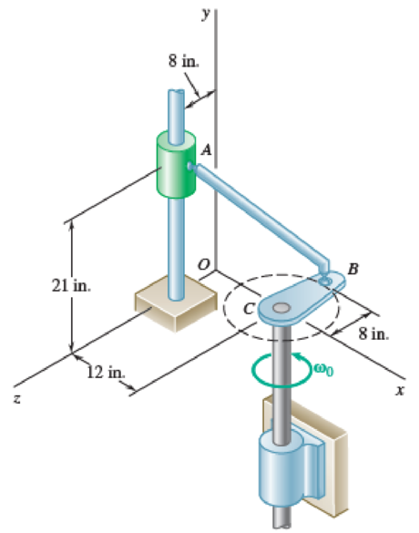
Fig. P15.207
Expert Solution & Answer
Want to see the full answer?
Check out a sample textbook solution
Students have asked these similar questions
A triangular distributed load of max intensity w acts on beam
AB. The beam is supported by a pin at A and member CD,
which is connected by pins at C and D respectively.
Determine the largest load intensity, Wmax, that can be
applied if the pin at D can support a maximum force of
18000 N. Also determine the reactions at A and C
and express each answer in Cartesian components. Assume
the masses of both beam and member ✓ are
negligible.
Dwas
шал
=
A
BY NC SA
2016 Eric Davishahl
C
D
-a-
Ур
-b-
X
B
W
Values for dimensions on the figure are given in the following
table. Note the figure may not be to scale.
Variable Value
a
6.6 m
b
11.88 m
C
4.29 m
The maximum load intensity is
=
wmax
N/m.
The reaction at A is A =
The reaction at C is
=
i+
Ĵ N.
ĴN.
12
i+
The beam is supported by a pin at B and a roller at C and is
subjected to the loading shown with w =110 lb/ft, and F
205 lb.
a.) If M
=
2,590 ft-lb, determine the support reactions at B
and C. Report your answers in both Cartesian components.
b.) Determine the largest magnitude of the applied couple M
for which the beam is still properly supported in equilibrium
with the pin and roller as shown.
2013 Michael Swanbom
CC
BY NC SA
M
ру
W
B⚫
C
F
ka
b
Values for dimensions on the figure are given in the following
table. Note the figure may not be to scale.
Variable Value
a
3.2 ft
b
6.4 ft
C
3 ft
a.) The reaction at B is B =
The reaction at C is C =
ĵ lb.
i+
Ĵ lb.
b.) The largest couple that can be applied is M
ft-lb.
==
i+
The beam ABC has a mass of 79.0 kg and is supported by
the rope BDC that runs through the frictionless pulley at D
. The winch at C has a mass of 36.5 kg. The tension in the
rope acts on the beam at points B and C and counteracts
the moments due to the beam's weight (acting vertically at
the midpoint of its length) and the weight of the winch
(acting vertically at point C) such that the resultant moment
about point A is equal to zero. Assume that rope segment
CD is vertical and note that rope segment BD is NOT
necessarily perpendicular to the beam.
a.) Compute the tension in the rope.
b.) Model the two forces the rope exerts on the beam as a
single equivalent force and couple moment acting at point B.
Enter your answer in Cartesian components.
c.) Model the two forces the rope exerts on the beam as a
single equivalent force (no couple) and determine the
distance from A to the point along the beam where the
equivalent force acts (measured parallel to the beam from A
). Enter your answer…
Chapter 15 Solutions
VECTOR MECH...,STAT.+DYNA.(LL)-W/ACCESS
Ch. 15.1 - A rectangular plate swings from arms of equal...Ch. 15.1 - Knowing that wheel A rotates with a constant...Ch. 15.1 - Prob. 15.1PCh. 15.1 - The motion of an oscillating flywheel is defined...Ch. 15.1 - The motion of an oscillating flywheel is defined...Ch. 15.1 - 15.4 The rotor of a gas turbine is rotating at a...Ch. 15.1 - A small grinding wheel is attached to the shaft of...Ch. 15.1 - A connecting rod is supported by a knife-edge at...Ch. 15.1 - Prob. 15.7PCh. 15.1 - The angular acceleration of an oscillating disk is...
Ch. 15.1 - The angular acceleration of a shaft is defined by...Ch. 15.1 - Prob. 15.10PCh. 15.1 - Prob. 15.11PCh. 15.1 - Prob. 15.12PCh. 15.1 - The rectangular block shown rotates about the...Ch. 15.1 - A circular plate of 120-mm radius is supported by...Ch. 15.1 - Prob. 15.15PCh. 15.1 - Prob. 15.16PCh. 15.1 - The earth makes one complete revolution on its...Ch. 15.1 - Prob. 15.18PCh. 15.1 - Prob. 15.19PCh. 15.1 - Prob. 15.20PCh. 15.1 - The rated speed of drum B of the belt sander shown...Ch. 15.1 - The two pulleys shown may be operated with the V...Ch. 15.1 - Prob. 15.23PCh. 15.1 - A gear reduction system consists of three gears A,...Ch. 15.1 - A belt is pulled to the right between cylinders A...Ch. 15.1 - Prob. 15.26PCh. 15.1 - Prob. 15.27PCh. 15.1 - A plastic film moves over two drums. During a 4-s...Ch. 15.1 - Cylinder A is moving downward with a velocity of 3...Ch. 15.1 - The system shown is held at rest by the...Ch. 15.1 - A load is to be raised 20 ft by the hoisting...Ch. 15.1 - A simple friction drive consists of two disks A...Ch. 15.1 - Prob. 15.33PCh. 15.1 - Two friction disks A and B are to be brought into...Ch. 15.1 - Two friction disks A and B are brought into...Ch. 15.1 - Steel tape is being wound onto a spool that...Ch. 15.1 - In a continuous printing process, paper is drawn...Ch. 15.2 - The ball rolls without slipping on the fixed...Ch. 15.2 - Three uniform rodsABC, DCE, and FGHare connected...Ch. 15.2 - Prob. 15.38PCh. 15.2 - Prob. 15.39PCh. 15.2 - A painter is halfway up a 10-m ladder when the...Ch. 15.2 - Rod AB can slide freely along the floor and the...Ch. 15.2 - Rod AB can slide freely along the floor and the...Ch. 15.2 - Rod AB moves over a small wheel at C while end A...Ch. 15.2 - The disk shown moves in the xy plane. Knowing that...Ch. 15.2 - The disk shown moves in the xy plane. Knowing that...Ch. 15.2 - Prob. 15.46PCh. 15.2 - Velocity sensors are placed on a satellite that is...Ch. 15.2 - In the planetary gear system shown, the radius of...Ch. 15.2 - Prob. 15.49PCh. 15.2 - 15.50 Arm AB rotates with an angular velocity of...Ch. 15.2 - Prob. 15.51PCh. 15.2 - A simplified gear system for a mechanical watch is...Ch. 15.2 - 15.53 and 15.54Arm ACB rotates about point C with...Ch. 15.2 - 15.53 and 15.54Arm ACB rotates about point C with...Ch. 15.2 - 15.55 Knowing that at the instant shown the...Ch. 15.2 - Prob. 15.56PCh. 15.2 - Knowing that the disk has a constant angular...Ch. 15.2 - The disk has a constant angular velocity of 20...Ch. 15.2 - The test rig shown was developed to perform...Ch. 15.2 - Prob. 15.60PCh. 15.2 - In the engine system shown, l = 160 mm and b = 60...Ch. 15.2 - In the engine system shown, l = 160 mm and b = 60...Ch. 15.2 - Prob. 15.63PCh. 15.2 - Prob. 15.64PCh. 15.2 - Prob. 15.65PCh. 15.2 - Prob. 15.66PCh. 15.2 - Prob. 15.67PCh. 15.2 - Prob. 15.68PCh. 15.2 - 15.69 In the position shown, bar DE has a constant...Ch. 15.2 - Both 6-in.-radius wheels roll without slipping on...Ch. 15.2 - The 80-mm-radius wheel shown rolls to the left...Ch. 15.2 - For the gearing shown, derive an expression for...Ch. 15.3 - The disk rolls without sliding on the fixed...Ch. 15.3 - Prob. 15.6CQCh. 15.3 - A juggling club is thrown vertically into the air....Ch. 15.3 - At the instant shown during deceleration, the...Ch. 15.3 - A helicopter moves horizontally in the x direction...Ch. 15.3 - Prob. 15.76PCh. 15.3 - Prob. 15.77PCh. 15.3 - Prob. 15.78PCh. 15.3 - Prob. 15.79PCh. 15.3 - The arm ABC rotates with an angular velocity of 4...Ch. 15.3 - The double gear rolls on the stationary left rack...Ch. 15.3 - Prob. 15.82PCh. 15.3 - Rod ABD is guided by wheels at A and B that roll...Ch. 15.3 - 15.84 Rod BDE is partially guided by a roller at D...Ch. 15.3 - Prob. 15.85PCh. 15.3 - Prob. 15.86PCh. 15.3 - Prob. 15.88PCh. 15.3 - Small wheels have been attached to the ends of bar...Ch. 15.3 - Prob. 15.90PCh. 15.3 - The disk is released from rest and rolls down the...Ch. 15.3 - Prob. 15.92PCh. 15.3 - Two identical rods ABF and DBE are connected by a...Ch. 15.3 - Arm ABD is connected by pins to a collar at B and...Ch. 15.3 - 15.95 Two 25-in. rods are pin-connected at D as...Ch. 15.3 - Prob. 15.96PCh. 15.3 - At the instant shown, the velocity of collar A is...Ch. 15.3 - Prob. 15.98PCh. 15.3 - Describe the space centrode and the body centrode...Ch. 15.3 - Describe the space centrode and the body centrode...Ch. 15.3 - Prob. 15.101PCh. 15.3 - Using the method of Sec. 15.3, solve Prob. 15.64....Ch. 15.3 - Using the method of Sec. 15.3, solve Prob. 15.65....Ch. 15.3 - Using the method of Sec. 15.3, solve Prob. 15.38....Ch. 15.4 - A rear-wheel-drive car starts from rest and...Ch. 15.4 - Fig. P15.105 and P15.106 15.105A 5-m steel beam is...Ch. 15.4 - For a 5-m steel beam AE, the acceleration of point...Ch. 15.4 - A 900-mm rod rests on a horizontal table. A force...Ch. 15.4 - In Prob. 15.107, determine the point of the rod...Ch. 15.4 - 15.109 Knowing that at the instant shown crank BC...Ch. 15.4 - Prob. 15.110PCh. 15.4 - Prob. 15.111PCh. 15.4 - The 18-in.-radius flywheel is rigidly attached to...Ch. 15.4 - 15.113 and 15.114 A 3-in.-radius drum is rigidly...Ch. 15.4 - Prob. 15.114PCh. 15.4 - A heavy crate is being moved a short distance...Ch. 15.4 - Prob. 15.116PCh. 15.4 - The 100-mm-radius drum rolls without slipping on a...Ch. 15.4 - In the planetary gear system shown, the radius of...Ch. 15.4 - The 200-mm-radius disk rolls without sliding on...Ch. 15.4 - Knowing that crank AB rotates about point A with a...Ch. 15.4 - Knowing that crank AB rotates about point A with a...Ch. 15.4 - In the two-cylinder air compressor shown, the...Ch. 15.4 - 15.123 The disk shown has a constant angular...Ch. 15.4 - Arm AB has a constant angular velocity of 16 rad/s...Ch. 15.4 - Arm AB has a constant angular velocity of 16 rad/s...Ch. 15.4 - A straight rack rests on a gear of radius r = 3...Ch. 15.4 - The elliptical exercise machine has fixed axes of...Ch. 15.4 - The elliptical exercise machine has fixed axes of...Ch. 15.4 - Prob. 15.129PCh. 15.4 - Prob. 15.130PCh. 15.4 - 15.131 and 15.132 Knowing that at the instant...Ch. 15.4 - 15.132 Knowing that at the instant shown bar AB...Ch. 15.4 - Prob. 15.133PCh. 15.4 - Prob. 15.134PCh. 15.4 - Prob. 15.135PCh. 15.4 - For the oil pump rig shown, link AB causes the...Ch. 15.4 - Denoting by rA the position vector of a point A of...Ch. 15.4 - Prob. 15.138PCh. 15.4 - Prob. 15.139PCh. 15.4 - Prob. 15.140PCh. 15.4 - Prob. 15.141PCh. 15.4 - Prob. 15.142PCh. 15.4 - Prob. 15.143PCh. 15.4 - Crank AB rotates with a constant clockwise angular...Ch. 15.4 - Crank AB rotates with a constant clockwise angular...Ch. 15.4 - Solve the engine system from Sample Prob. 15.15...Ch. 15.4 - Prob. 15.147PCh. 15.4 - Prob. 15.148PCh. 15.4 - Prob. 15.149PCh. 15.5 - A person walks radially inward on a platform that...Ch. 15.5 - Prob. 15.150PCh. 15.5 - Prob. 15.151PCh. 15.5 - 15.152 and 15.153Two rotating rods are connected...Ch. 15.5 - 15.152 and 15.153Two rotating rods are connected...Ch. 15.5 - Pin P is attached to the wheel shown and slides in...Ch. 15.5 - Knowing that at the instant shown the angular...Ch. 15.5 - Prob. 15.156PCh. 15.5 - The motion of pin P is guided by slots cut in rods...Ch. 15.5 - Prob. 15.158PCh. 15.5 - Prob. 15.159PCh. 15.5 - Prob. 15.160PCh. 15.5 - Pin P is attached to the collar shown; the motion...Ch. 15.5 - Prob. 15.162PCh. 15.5 - Prob. 15.163PCh. 15.5 - At the instant shown, the length of the boom AB is...Ch. 15.5 - At the instant shown, the length of the boom AB is...Ch. 15.5 - Prob. 15.166PCh. 15.5 - Prob. 15.167PCh. 15.5 - Prob. 15.168PCh. 15.5 - 15.168 and 15.169A chain is looped around two...Ch. 15.5 - Prob. 15.170PCh. 15.5 - Prob. 15.171PCh. 15.5 - The collar P slides outward at a constant relative...Ch. 15.5 - Pin P slides in a circular slot cut in the plate...Ch. 15.5 - Prob. 15.174PCh. 15.5 - Prob. 15.175PCh. 15.5 - Knowing that at the instant shown the rod attached...Ch. 15.5 - Prob. 15.177PCh. 15.5 - In Prob. 15.177, determine the angular velocity...Ch. 15.5 - At the instant shown, bar BC has an angular...Ch. 15.5 - Prob. 15.180PCh. 15.5 - Rod AB passes through a collar that is welded to...Ch. 15.5 - Prob. 15.182PCh. 15.5 - Prob. 15.183PCh. 15.6 - The bowling ball shown rolls without slipping on...Ch. 15.6 - Prob. 15.185PCh. 15.6 - Prob. 15.186PCh. 15.6 - Prob. 15.187PCh. 15.6 - The rotor of an electric motor rotates at the...Ch. 15.6 - Prob. 15.189PCh. 15.6 - Prob. 15.190PCh. 15.6 - In the system shown, disk A is free to rotate...Ch. 15.6 - Prob. 15.192PCh. 15.6 - Prob. 15.193PCh. 15.6 - Prob. 15.194PCh. 15.6 - A 3-in.-radius disk spins at the constant rate 2 =...Ch. 15.6 - Prob. 15.196PCh. 15.6 - The cone shown rolls on the zx plane with its apex...Ch. 15.6 - At the instant shown, the robotic arm ABC is being...Ch. 15.6 - Prob. 15.199PCh. 15.6 - Prob. 15.200PCh. 15.6 - Several rods are brazed together to form the...Ch. 15.6 - In Prob. 15.201, the speed of point B is known to...Ch. 15.6 - Prob. 15.203PCh. 15.6 - Prob. 15.204PCh. 15.6 - Rod BC and BD are each 840 mm long and are...Ch. 15.6 - Rod AB is connected by ball-and-socket joints to...Ch. 15.6 - Prob. 15.207PCh. 15.6 - Prob. 15.208PCh. 15.6 - Prob. 15.209PCh. 15.6 - Prob. 15.210PCh. 15.6 - Prob. 15.211PCh. 15.6 - Prob. 15.212PCh. 15.6 - Prob. 15.213PCh. 15.6 - Prob. 15.214PCh. 15.6 - In Prob. 15.205, determine the acceleration of...Ch. 15.6 - In Prob. 15.206, determine the acceleration of...Ch. 15.6 - In Prob. 15.207, determine the acceleration of...Ch. 15.6 - Prob. 15.218PCh. 15.6 - Prob. 15.219PCh. 15.7 - A flight simulator is used to train pilots on how...Ch. 15.7 - A flight simulator is used to train pilots on how...Ch. 15.7 - Prob. 15.222PCh. 15.7 - Prob. 15.223PCh. 15.7 - Prob. 15.224PCh. 15.7 - The bent rod shown rotates at the constant rate of...Ch. 15.7 - The bent pipe shown rotates at the constant rate 1...Ch. 15.7 - The circular plate shown rotates about its...Ch. 15.7 - Prob. 15.228PCh. 15.7 - Prob. 15.229PCh. 15.7 - Prob. 15.230PCh. 15.7 - Prob. 15.231PCh. 15.7 - Using the method of Sec. 15.7A, solve Prob....Ch. 15.7 - Prob. 15.233PCh. 15.7 - Prob. 15.234PCh. 15.7 - Prob. 15.235PCh. 15.7 - The arm AB of length 16 ft is used to provide an...Ch. 15.7 - The remote manipulator system (RMS) shown is used...Ch. 15.7 - A disk with a radius of 120 mm rotates at the...Ch. 15.7 - Prob. 15.239PCh. 15.7 - Prob. 15.240PCh. 15.7 - Prob. 15.241PCh. 15.7 - Prob. 15.242PCh. 15.7 - Prob. 15.243PCh. 15.7 - Prob. 15.244PCh. 15.7 - Prob. 15.245PCh. 15.7 - Prob. 15.246PCh. 15.7 - Prob. 15.247PCh. 15 - A wheel moves in the xy plane in such a way that...Ch. 15 - Two blocks and a pulley are connected by...Ch. 15 - A baseball pitching machine is designed to deliver...Ch. 15 - Prob. 15.251RPCh. 15 - Prob. 15.252RPCh. 15 - Knowing that at the instant shown rod AB has zero...Ch. 15 - Rod AB is attached to a collar at A and is fitted...Ch. 15 - Prob. 15.255RPCh. 15 - A disk of 0.15-m radius rotates at the constant...Ch. 15 - Prob. 15.257RPCh. 15 - Prob. 15.258RPCh. 15 - In the position shown, the thin rod moves at a...
Additional Engineering Textbook Solutions
Find more solutions based on key concepts
A nozzle at A discharges water with an initial velocity of 36 ft/s at an angle with the horizontal. Determine ...
Vector Mechanics For Engineers
The solid steel shaft AC has a diameter of 25 mm and is supported by smooth bearings at D and E. It is coupled ...
Mechanics of Materials (10th Edition)
Why is the study of database technology important?
Database Concepts (8th Edition)
What are the design issues for character string types?
Concepts Of Programming Languages
Convert each of the following binary representations to its equivalent base ten form: a. 101010 b. 100001 c. 10...
Computer Science: An Overview (13th Edition) (What's New in Computer Science)
Comprehension Check 7-14
The power absorbed by a resistor can be given by P = I2R, where P is power in units of...
Thinking Like an Engineer: An Active Learning Approach (4th Edition)
Knowledge Booster


Learn more about
Need a deep-dive on the concept behind this application? Look no further. Learn more about this topic, mechanical-engineering and related others by exploring similar questions and additional content below.Similar questions
- w1 Three distributed loads act on a beam as shown. The load between A and B increases linearly from 0 to a maximum intensity of w₁ = 12.8 lb/ft at point B. The load then varies linearly with a different slope to an intensity of w₂ = 17.1 lb/ft at C. The load intensity in section CD of the beam is constant at w3 10.2 lb/ft. For each load region, determine the resultant force and the location of its line of action (distance to the right of A for all cases). cc 10 BY NC SA 2016 Eric Davishahl = WI W2 W3 -b- C Values for dimensions on the figure are given in the following table. Note the figure may not be to scale. Variable Value a 4.50 ft b 5.85 ft с 4.28 ft The resultant load in region AB is FR₁ = lb and acts ft to the right of A. The resultant load in region BC is FR2 lb and acts = ft to the right of A. The resultant load in region CD is FR3 = lb and acts ft to the right of A.arrow_forwardThe T-shaped structure is embedded in a concrete wall at A and subjected to the force F₁ and the force-couple system F2 1650 N and M = 1,800 N-m at the locations shown. Neglect the weight of the structure in your calculations for this problem. = a.) Compute the allowable range of magnitudes for F₁ in the direction shown if the connection at A will fail when subjected to a resultant moment with a magnitude of 920 N- m or higher. b.) Focusing on the forces and igonoring given M for now. Using the value for F1, min that you calculated in (a), replace the two forces F₁ and F2 with a single force that has equivalent effect on the structure. Specify the equivalent →> force Feq in Cartesian components and indicate the horizontal distance from point A to its line of action (note this line of action may not intersect the structure). c.) Now, model the entire force system (F1,min, F2, and M) as a single force and couple acting at the junction of the horizontal and vertical sections of the…arrow_forwardThe heated rod from Problem 3 is subject to a volumetric heating h(x) = h0 x L in units of [Wm−3], as shown in the figure below. Under the heat supply the temperature of the rod changes along x with the temperature function T (x). The temperature T (x) is governed by the d following equations: − dx (q(x)) + h(x) = 0 PDE q(x) =−k dT dx Fourier’s law of heat conduction (4) where q(x) is the heat flux through the rod and k is the (constant) thermal conductivity. Both ends of the bar are in contact with a heat reservoir at zero temperature. Determine: 1. Appropriate BCs for this physical problem. 2. The temperature function T (x). 3. The heat flux function q(x). Side Note: Please see that both ends of bar are in contact with a heat reservoir at zero temperature so the boundary condition at the right cannot be du/dx=0 because its not thermally insulated. Thank youarrow_forward
- The elastic bar from Problem 1 spins with angular velocity ω about an axis, as shown in the figure below. The radial acceleration at a generic point x along the bar is a(x) = ω2x. Under this radial acceleration, the bar stretches along x with displacement function u(x). The displacement d u(x) is governed by the following equations: dx (σ(x)) + ρa(x) = 0 PDE σ(x) = E du dx Hooke’s law (2) where σ(x) is the axial stress in the rod, ρ is the mass density, and E is the (constant) Young’s modulus. The bar is pinned on the rotation axis at x = 0 and it is also pinned at x = L. Determine: 1. Appropriate BCs for this physical problem. 2. The displacement function u(x). 3. The stress function σ(x). SIDE QUESTION: I saw a tutor solve it before but I didn't understand why the tutor did not divide E under the second term (c1x) before finding u(x). The tutor only divided E under first term. please explain and thank youarrow_forwardcalculate the total power required to go 80 mph in a VW Type 2 Samba Bus weighing 2310 lbs. with a Cd of 0.35 and a frontal area of 30ft^2. Consider the coefficient of rolling resistance to be 0.018. What is the increase in power required to go the same speed if the weight is increased by 2205 pounds (the rated carrying capacity of the vehicle). If the rated power for the vehicle is 49 bhp, will the van be able to reach 80 mph at full carrying capacity?arrow_forwardA distillation column with a total of 13 actual stages (including a partial condenser) is used to perform a separation which requires 7 ideal stages. Calculate the overall column efficiency, and report your answer in %arrow_forward
- 6. Consider a 10N step input to the mechanical system shown below, take M = 15kg, K = 135N/m, and b = 0.4 Ns/m. (a) Assume zero initial condition, calculate the (i) System pole (ii) System characterization, and (iii) The time domain response (b) Calculate the steady-state value of the system b [ www K 个 х M -F(+)arrow_forward2. Solve the following linear time invariant differential equations using Laplace transforms subject to different initial conditions (a) y-y=t for y(0) = 1 and y(0) = 1 (b) ÿ+4y+ 4y = u(t) for y(0) = 0 and y(0) = 1 (c) y-y-2y=0 for y(0) = 1 and y(0) = 0arrow_forward3. For the mechanical systems shown below, the springs are undeflected when x₁ = x2 = x3 = 0 and the input is given as fa(t). Draw the free-body diagrams and write the modeling equations governing each of the systems. K₁ 000 K₂ 000 M₁ M2 -fa(t) B₂ B₁ (a) fa(t) M2 K₂ 000 B K₁ x1 000 M₁ (b)arrow_forward
- This question i m uploading second time . before you provide me incorrect answer. read the question carefully and solve accordily.arrow_forward1. Create a table comparing five different analogous variables for translational, rotational, electrical and fluid systems. Include the standard symbols for each variable in their respective systems.arrow_forward2) Suppose that two unequal masses m₁ and m₂ are moving with initial velocities v₁ and v₂, respectively. The masses hit each other and have a coefficient of restitution e. After the impact, mass 1 and 2 head to their respective gaps at angles a and ẞ, respectively. Derive expressions for each of the angles in terms of the initial velocities and the coefficient of restitution. m1 m2 8 m1 m2 βarrow_forward
arrow_back_ios
SEE MORE QUESTIONS
arrow_forward_ios
Recommended textbooks for you
 Elements Of ElectromagneticsMechanical EngineeringISBN:9780190698614Author:Sadiku, Matthew N. O.Publisher:Oxford University Press
 Mechanics of Materials (10th Edition)Mechanical EngineeringISBN:9780134319650Author:Russell C. HibbelerPublisher:PEARSON
 Thermodynamics: An Engineering ApproachMechanical EngineeringISBN:9781259822674Author:Yunus A. Cengel Dr., Michael A. BolesPublisher:McGraw-Hill Education
 Control Systems EngineeringMechanical EngineeringISBN:9781118170519Author:Norman S. NisePublisher:WILEY
 Mechanics of Materials (MindTap Course List)Mechanical EngineeringISBN:9781337093347Author:Barry J. Goodno, James M. GerePublisher:Cengage Learning
 Engineering Mechanics: StaticsMechanical EngineeringISBN:9781118807330Author:James L. Meriam, L. G. Kraige, J. N. BoltonPublisher:WILEY
Elements Of Electromagnetics
Mechanical Engineering
ISBN:9780190698614
Author:Sadiku, Matthew N. O.
Publisher:Oxford University Press
Mechanics of Materials (10th Edition)
Mechanical Engineering
ISBN:9780134319650
Author:Russell C. Hibbeler
Publisher:PEARSON
Thermodynamics: An Engineering Approach
Mechanical Engineering
ISBN:9781259822674
Author:Yunus A. Cengel Dr., Michael A. Boles
Publisher:McGraw-Hill Education
Control Systems Engineering
Mechanical Engineering
ISBN:9781118170519
Author:Norman S. Nise
Publisher:WILEY
Mechanics of Materials (MindTap Course List)
Mechanical Engineering
ISBN:9781337093347
Author:Barry J. Goodno, James M. Gere
Publisher:Cengage Learning
Engineering Mechanics: Statics
Mechanical Engineering
ISBN:9781118807330
Author:James L. Meriam, L. G. Kraige, J. N. Bolton
Publisher:WILEY
Differences between Temporary Joining and Permanent Joining.; Author: Academic Gain Tutorials;https://www.youtube.com/watch?v=PTr8QZhgXyg;License: Standard Youtube License