Statics and Mechanics of Materials (5th Edition)
5th Edition
ISBN: 9780134382593
Author: Russell C. Hibbeler
Publisher: PEARSON
expand_more
expand_more
format_list_bulleted
Concept explainers
Textbook Question
Chapter 15.2, Problem 6FP
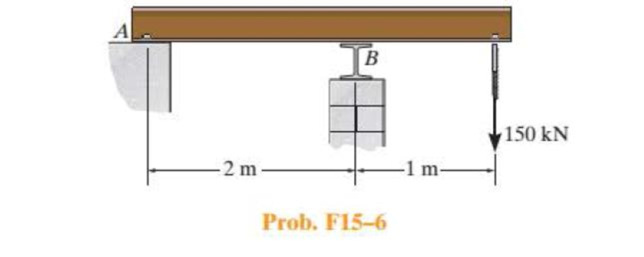
Select the lightest W410-shaped section that can safely support the load. The beam is made of steel having an allowable normal stress of σallow = 150 MPa and an allowable shear stress of τallow = 75 MPa. Assume the beam is pinned at A and roller supported at B.

Expert Solution & Answer
Want to see the full answer?
Check out a sample textbook solution
Students have asked these similar questions
PLEASE SOLVE STEP BY STEP WITHOUT ARTIFICIAL INTELLIGENCE OR CHATGPT
SOLVE BY HAND STEP BY STEP
PLEASE SOLVE STEP BY STEP WITHOUT ARTIFICIAL INTELLIGENCE OR CHATGPT
SOLVE BY HAND STEP BY STEP
PLEASE SOLVE STEP BY STEP WITHOUT ARTIFICIAL INTELLIGENCE OR CHATGPT
SOLVE BY HAND STEP BY STEP
Chapter 15 Solutions
Statics and Mechanics of Materials (5th Edition)
Ch. 15.2 - Determine the minimum dimension a to the nearest...Ch. 15.2 - Prob. 2FPCh. 15.2 - Prob. 3FPCh. 15.2 - Determine the minimum dimension h to the nearest...Ch. 15.2 - Prob. 5FPCh. 15.2 - Select the lightest W410-shaped section that can...Ch. 15.2 - The beam is made of timber that has an allowable...Ch. 15.2 - Determine the minimum width of the beam to the...Ch. 15.2 - Determine the minimum width of the beam to the...Ch. 15.2 - The brick wall exerts a uniform distributed load...
Ch. 15.2 - Select the lightest-weight wide-flange beam from...Ch. 15.2 - Prob. 6PCh. 15.2 - Select the lightest-weight wide-flange beam with...Ch. 15.2 - Select the lightest-weight wide-flange beam from...Ch. 15.2 - Select the lightest W360 wide-flange beam from...Ch. 15.2 - Investigate if the W250 58 beam can safely...Ch. 15.2 - The beam is constructed from two boards. If each...Ch. 15.2 - The joists of a floor in a warehouse are to be...Ch. 15.2 - The timber beam has a width of 6 in. Determine its...Ch. 15.2 - The beam is constructed from four boards. If each...Ch. 15.2 - The beam is constructed from two boards. If each...Ch. 15.2 - If the cable is subjected to a maximum force of P...Ch. 15.2 - If the W360 45 wide-flange beam has an allowable...Ch. 15.2 - If P = 800 lb, determine the minimum dimension a...Ch. 15.2 - If a = 3 in. and the wood has an allowable normal...Ch. 15.2 - The beam is constructed from three plastic strips....Ch. 15.2 - If the allowable bending stress is allow = 6 MPa,...Ch. 15.2 - The beam is made of Douglas fir having an...Ch. 15.2 - Select the lightest-weight wide-flange beam from...Ch. 15.2 - Draw the shear and moment diagrams for the shaft,...Ch. 15.2 - Draw the shear and moment diagrams for the shaft,...
Knowledge Booster
Learn more about
Need a deep-dive on the concept behind this application? Look no further. Learn more about this topic, mechanical-engineering and related others by exploring similar questions and additional content below.Similar questions
- Consider the bar, shown in Figure 1 that undergoes axial displacement due to both a distributed load and a point force. The bar is of cross-sectional area A = 1.10-3 m², and has a modulus of elasticity E = 100 GPa. 1(x) = 5 kN/m x=0.0 x=2.0 2.0m 10 kN Figure 1: Bar domain with varying distributed forces. a) The general form of the governing equations describing the bar's displacement, u(x), is given by, d (AE du(x)) -) +1(x) = 0. d.x dx What are the accompanying boundary conditions for this bar? b) Using the mesh in Figure 2, form the basis functions associated with element 2 and write the FEM approximation over the element. 1 2 3 1 2 1m 1m Figure 2: Mesh of 2 elements. Elements are numbered with underlines. c) The general form of the element stiffness matrix system, with nodes indexed by i and j, is, AE Uj N;(x)l(x)dx – Ng(0)f(0) ¥ [4]}]{{}}={{{}\(\\+} + {N(2)f(2) = N (0)5() }, (1) 0, respectively. L = (2) where f(2) and f(0) denote the boundary forces at positions x 2 and x Evaluate…arrow_forwardanswer pleasearrow_forwardamination) Question 1 Consider the bar, shown in Figure 1, that undergoes axial displacement due to both a distributed load and a point force. The bar is of cross-sectional area A = 1.103 m2, and has a modulus of elasticity E = 100 GPa. 1(x) = 5 kN/m 10 kN X x=0.0 x=2.0 2.0m Figure 1: Bar domain with varying distributed forces. a) The general form of the governing equations describing the bar's displacement, u(x), is given by, d (AE du(x)) + 1(x) = 0. dx dx What are the accompanying boundary conditions for this bar? MacBook Air a 会 DII F5 F6 F7 F8 80 F3 F4 0/ 20 [8 marksl 8 FOarrow_forward
- show workingarrow_forwardCFD help Figure 3: Advection equation, solution for three different timesteps. Q1) Provide an explanation what conditions and numerical setup could explain the curves. Identify which of the three curves is the first, second and third timestep.arrow_forwardanswer pleasearrow_forward
- Figure 3 shows the numerical solution of the advection equation for a scalar u along x at three consecutive timesteps. 1.0 0.8- 0.6 0.4- 0.2 0.0 00 -0.2 -0.4 -0.6- 3.0 3.5 4.0 4.5 5.0 5.5 6.0 6.5 Figure 3: Advection equation, solution for three different timesteps.arrow_forwardQuestion 2 Figure 3 shows the numerical solution of the advection equation for a scalar u along x at three consecutive timesteps. 1.0 0.8- 0.6- 0.4- 0.2- 0.0- -0.2- -0.4- -0.6 3.0 3.5 4.0 4.5 5.0 5.5 6.0 6.5 Figure 3: Advection equation, solution for three different timesteps. a) Provide an explanation what conditions and numerical setup could explain the curves. Identify which of the three curves is the first, second and third timestep. b) Consider explicit schemes with central and upwind discretisations. Explain how each of these candidate discretisations could produce the behaviour shown in Figure 3. c) Determine the CFL number that was used in the simulation for each of the candidate schemes for all possible updates. Assume that the timestep and mesh-width used are constant. Read the data to two digits of accuracy from Figure 4 shown at the end of the question, which is an enlarged version of Figure 3. Demonstrate your method and input data for one calculation, but then use a…arrow_forwardanswer pleasearrow_forward
arrow_back_ios
SEE MORE QUESTIONS
arrow_forward_ios
Recommended textbooks for you
 Elements Of ElectromagneticsMechanical EngineeringISBN:9780190698614Author:Sadiku, Matthew N. O.Publisher:Oxford University Press
 Mechanics of Materials (10th Edition)Mechanical EngineeringISBN:9780134319650Author:Russell C. HibbelerPublisher:PEARSON
 Thermodynamics: An Engineering ApproachMechanical EngineeringISBN:9781259822674Author:Yunus A. Cengel Dr., Michael A. BolesPublisher:McGraw-Hill Education
 Control Systems EngineeringMechanical EngineeringISBN:9781118170519Author:Norman S. NisePublisher:WILEY
 Mechanics of Materials (MindTap Course List)Mechanical EngineeringISBN:9781337093347Author:Barry J. Goodno, James M. GerePublisher:Cengage Learning
 Engineering Mechanics: StaticsMechanical EngineeringISBN:9781118807330Author:James L. Meriam, L. G. Kraige, J. N. BoltonPublisher:WILEY

Elements Of Electromagnetics
Mechanical Engineering
ISBN:9780190698614
Author:Sadiku, Matthew N. O.
Publisher:Oxford University Press

Mechanics of Materials (10th Edition)
Mechanical Engineering
ISBN:9780134319650
Author:Russell C. Hibbeler
Publisher:PEARSON

Thermodynamics: An Engineering Approach
Mechanical Engineering
ISBN:9781259822674
Author:Yunus A. Cengel Dr., Michael A. Boles
Publisher:McGraw-Hill Education

Control Systems Engineering
Mechanical Engineering
ISBN:9781118170519
Author:Norman S. Nise
Publisher:WILEY

Mechanics of Materials (MindTap Course List)
Mechanical Engineering
ISBN:9781337093347
Author:Barry J. Goodno, James M. Gere
Publisher:Cengage Learning

Engineering Mechanics: Statics
Mechanical Engineering
ISBN:9781118807330
Author:James L. Meriam, L. G. Kraige, J. N. Bolton
Publisher:WILEY
Solids: Lesson 53 - Slope and Deflection of Beams Intro; Author: Jeff Hanson;https://www.youtube.com/watch?v=I7lTq68JRmY;License: Standard YouTube License, CC-BY