
Concept explainers
Find the member end moments and reaction for the frames.
Answer to Problem 30P
The end moments at the member AC
Explanation of Solution
Fixed end moment:
Formula to calculate the fixed moment for UDL is
Calculation:
Consider the flexural rigidity EI of the frame is constant.
Show the free body diagram of the entire frame as in Figure 1.
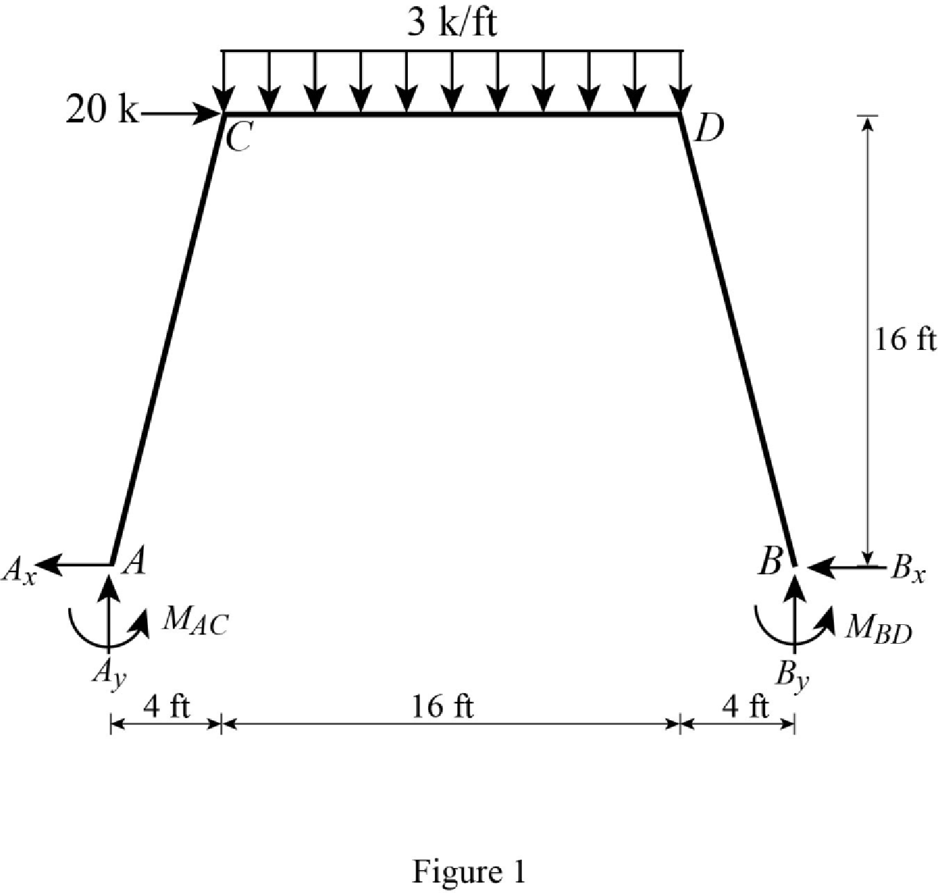
Refer Figure 1,
Calculate the fixed end moment for AC.
Calculate the fixed end moment for CA.
Calculate the fixed end moment for CD.
Calculate the fixed end moment for DC.
Calculate the fixed end moment for DB.
Calculate the fixed end moment for BD.
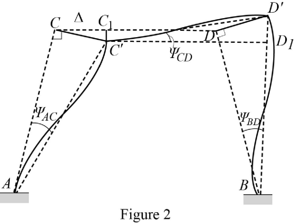
Chord rotations:
Show the free body diagram of the chord rotation of the frame as in Figure 2.
Calculate the length of AC by using Pythagoras theorem.
Calculate the length of BD by using Pythagoras theorem.
Calculate the chord rotation of the frame AC.
Calculate the chord rotation of the frame BD.
Calculate the chord rotation of the frame CD.
Calculate the slope deflection equation for the member AC.
Substitute 16.49 ft for L, 0 for
Calculate the slope deflection equation for the member CA.
Substitute 16.49 ft for L, 0 for
Calculate the slope deflection equation for the member CD.
Substitute 16 ft for L,
Calculate the slope deflection equation for the member DC.
Substitute 16 ft for L,
Calculate the slope deflection equation for the member DB.
Substitute 16.49 ft for L, 0 for
Calculate the slope deflection equation for the member BD.
Substitute 16.49 ft for L, 0 for
Write the equilibrium equation as below.
Substitute equation (2) and equation (3) in above equation.
Write the equilibrium equation as below.
Substitute equation (4) and equation (5) in above equation.
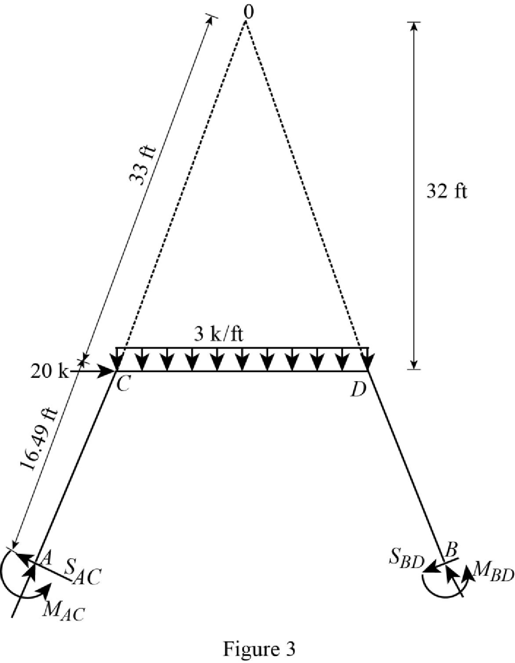
Show the free body diagram of the entire frame due to sway force as in Figure 3.
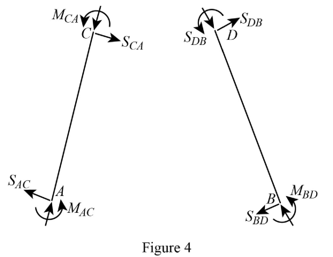
Show the free body diagram of the frame due to sway force as in Figure 4.
Calculate the horizontal reaction at the member AC due to sway force by taking moment about point A.
Calculate the horizontal reaction at the member BD due to sway force by taking moment about point B.
Calculate the reaction of the support C and support D due to sway force by taking the moment about O.
Substitute equation (1), equation (2), equation (5), and equation (6) in above equation.
Solve the equation (7), equation (8), and equation (9).
Calculate the moment about AC.
Substitute
Calculate the moment about CA.
Substitute
Calculate the moment about CD.
Substitute
Calculate the moment about DC.
Substitute
Calculate the moment about DB.
Substitute
Calculate the moment about BD.
Substitute
Show the section free body diagram of the member AC, CD and DB as in Figure 5.
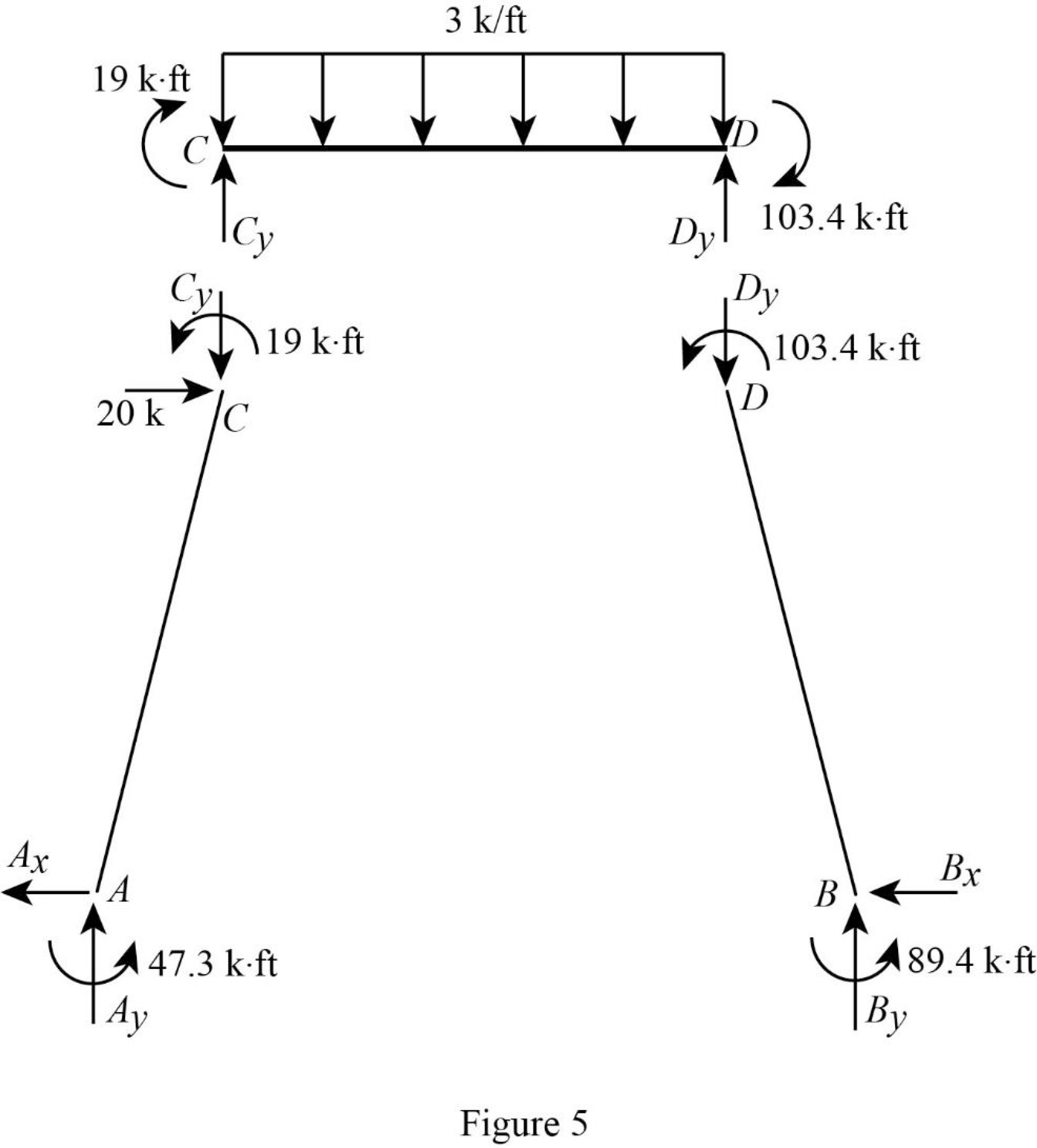
Consider the member CD.
Calculate the vertical reaction at the joint D by taking moment about point C.
Calculate the vertical reaction at joint C by resolving the vertical equilibrium.
Consider the member AC.
Calculate the vertical reaction at joint A by resolving the vertical equilibrium.
Calculate the horizontal reaction at the joint A by taking moment about point C.
Consider the member BD.
Calculate the vertical reaction at joint B by resolving the vertical equilibrium.
Consider the entire frame.
Calculate the horizontal reaction at the joint B by considering the horizontal equilibrium.
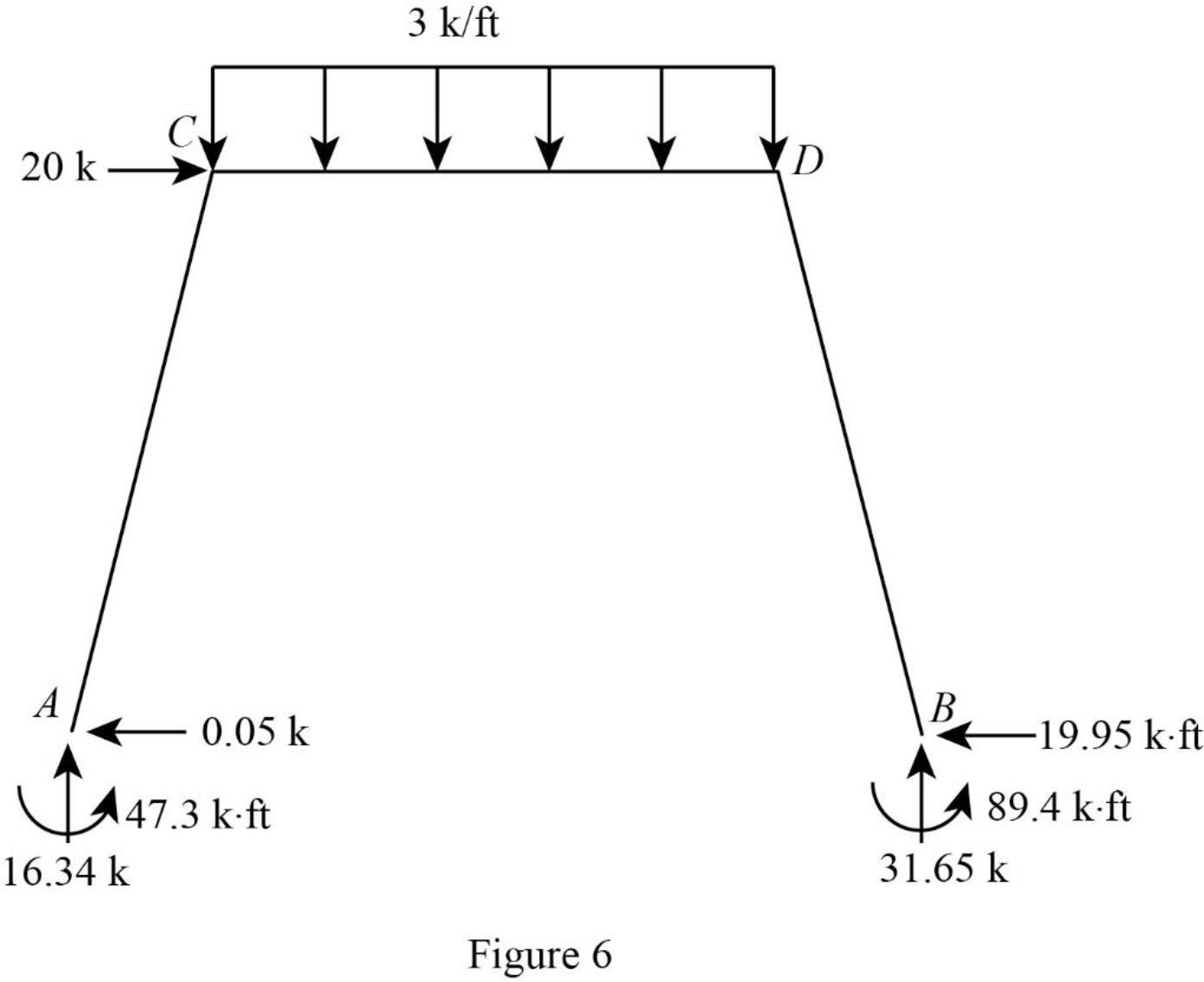
Show the reactions of the frame as in Figure 6.
Want to see more full solutions like this?
Chapter 15 Solutions
Structural Analysis (MindTap Course List)


- Determine the bending moment at support A for the beam shown using the slope-deflection method. Use the sign convention defined in the chapter. a. 232.9 k-ft b. -182.1 k-ft c. 182.1 k-ft d. -232.9 k-ftarrow_forwardWhat is the shear and normal stresses of Point J and Point K?arrow_forwardWhat are the states of stress (magnitude and tension/compression of the normal stresses and shear stress) at Point J and Point K?arrow_forward
- Consider, M people (aka pax) who want to travel by car from O to D. They all start working at D at Q (e.g., Q-8am). If a person departs at time t, assume the time needed to go from O to D is given by c(t)=A+Bx(t), where x(t) is the flow of people departing at time t [car/unit of time]. In addition, a is the penalty for being early at work (E(t) is how early the person arrived when departing at time t), and ẞ is the penalty for being late at work (L(t) is how late the person arrived when departing at time t). Assume 0 < a < 1 < ß. Further assume the departure time choice problem under the equilibrium conditions. Prove that the arrival time of people who depart when most of the M people start their trips is equal to Q.arrow_forwarda. A b. A 3. Sketch normal depth, critical depth and the water surface profile. Assume at A and B the water is flowing at normal depth. Label and Identify all curves (i.e., M1, S2, etc.) Yn > Ye Уп Ye Уп> Ус yarrow_forward2. Design a trapezoidal ditch to carry Q = 1000 cfs. The ditch will be a lined channel, gravel bottom with sides shown below on a slope of S = 0.009. The side slopes of the 20-ft wide ditch will be 1 vertical to 3 horizontal. a) Determine the normal depth of flow (yn) using the Normal value for Manning's n. b) If freeboard requirements are 25% of the normal depth, how deep should the ditch be constructed? c) Classify the slope. T b Уп Z 1 Yn + FBarrow_forwardP15.45 WP A stainless steel pipe (Figure P15.45) with an outside diameter of 2.375 in. and a wall thickness of 0.109 in. is subjected to a bending moment M = 50 lb ft and an internal pressure of 180 psi. Determine the absolute maximum shear stress on the outer surface of the pipe. M FIGURE P15.45 Marrow_forward10.72 What power must the pump supply to the system to pump the oil from the lower reservoir to the upper reservoir at a rate of 0.3 m³/s? Sketch the HGL and the EGL for the system. p=940 kg/m³ v = 10-5 m²/s Elevation 100 m Elevation 112 m L= 150 m Oil Steel pipe D = 30 cm Problem 10.72arrow_forwardL / 83° 28° $75°E M 202° Q2: The scanning process was completed from point J to point N. The direction of the straight line was LM and the angles of deviation are shown in the figure below. Find the direction of the remaining sides? Narrow_forwardarrow_back_iosSEE MORE QUESTIONSarrow_forward_ios
