
Concept explainers
Find the member end moments and reaction for the frames.
Answer to Problem 30P
The end moments at the member AC
Explanation of Solution
Fixed end moment:
Formula to calculate the fixed moment for UDL is
Calculation:
Consider the flexural rigidity EI of the frame is constant.
Show the free body diagram of the entire frame as in Figure 1.
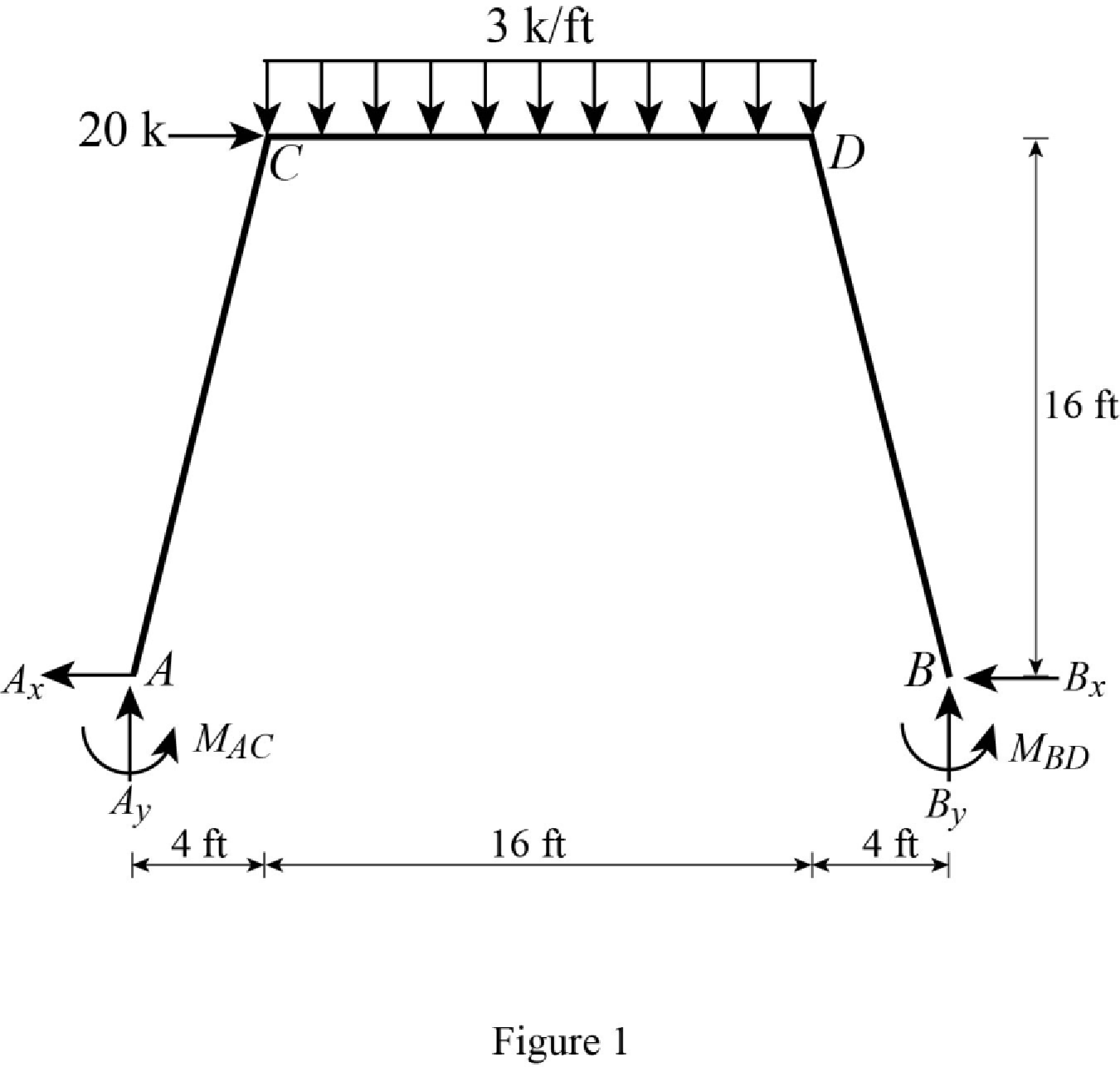
Refer Figure 1,
Calculate the fixed end moment for AC.
Calculate the fixed end moment for CA.
Calculate the fixed end moment for CD.
Calculate the fixed end moment for DC.
Calculate the fixed end moment for DB.
Calculate the fixed end moment for BD.
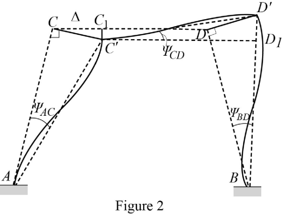
Chord rotations:
Show the free body diagram of the chord rotation of the frame as in Figure 2.
Calculate the length of AC by using Pythagoras theorem.
Calculate the length of BD by using Pythagoras theorem.
Calculate the chord rotation of the frame AC.
Calculate the chord rotation of the frame BD.
Calculate the chord rotation of the frame CD.
Calculate the slope deflection equation for the member AC.
Substitute 16.49 ft for L, 0 for
Calculate the slope deflection equation for the member CA.
Substitute 16.49 ft for L, 0 for
Calculate the slope deflection equation for the member CD.
Substitute 16 ft for L,
Calculate the slope deflection equation for the member DC.
Substitute 16 ft for L,
Calculate the slope deflection equation for the member DB.
Substitute 16.49 ft for L, 0 for
Calculate the slope deflection equation for the member BD.
Substitute 16.49 ft for L, 0 for
Write the equilibrium equation as below.
Substitute equation (2) and equation (3) in above equation.
Write the equilibrium equation as below.
Substitute equation (4) and equation (5) in above equation.
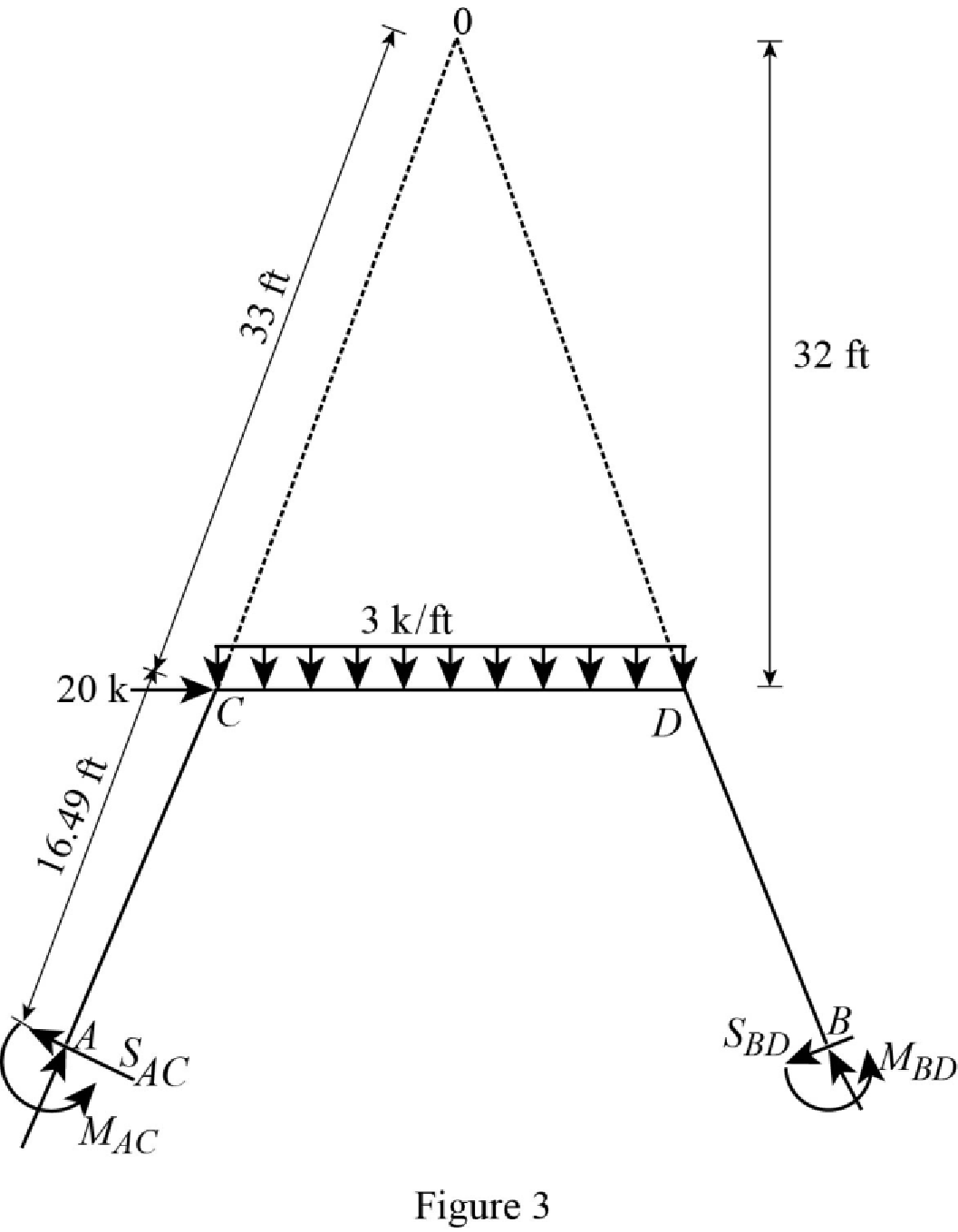
Show the free body diagram of the entire frame due to sway force as in Figure 3.
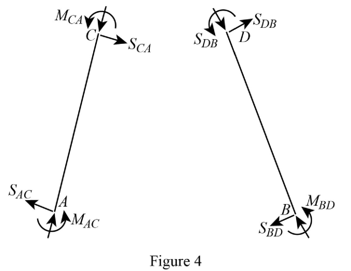
Show the free body diagram of the frame due to sway force as in Figure 4.
Calculate the horizontal reaction at the member AC due to sway force by taking moment about point A.
Calculate the horizontal reaction at the member BD due to sway force by taking moment about point B.
Calculate the reaction of the support C and support D due to sway force by taking the moment about O.
Substitute equation (1), equation (2), equation (5), and equation (6) in above equation.
Solve the equation (7), equation (8), and equation (9).
Calculate the moment about AC.
Substitute
Calculate the moment about CA.
Substitute
Calculate the moment about CD.
Substitute
Calculate the moment about DC.
Substitute
Calculate the moment about DB.
Substitute
Calculate the moment about BD.
Substitute
Show the section free body diagram of the member AC, CD and DB as in Figure 5.
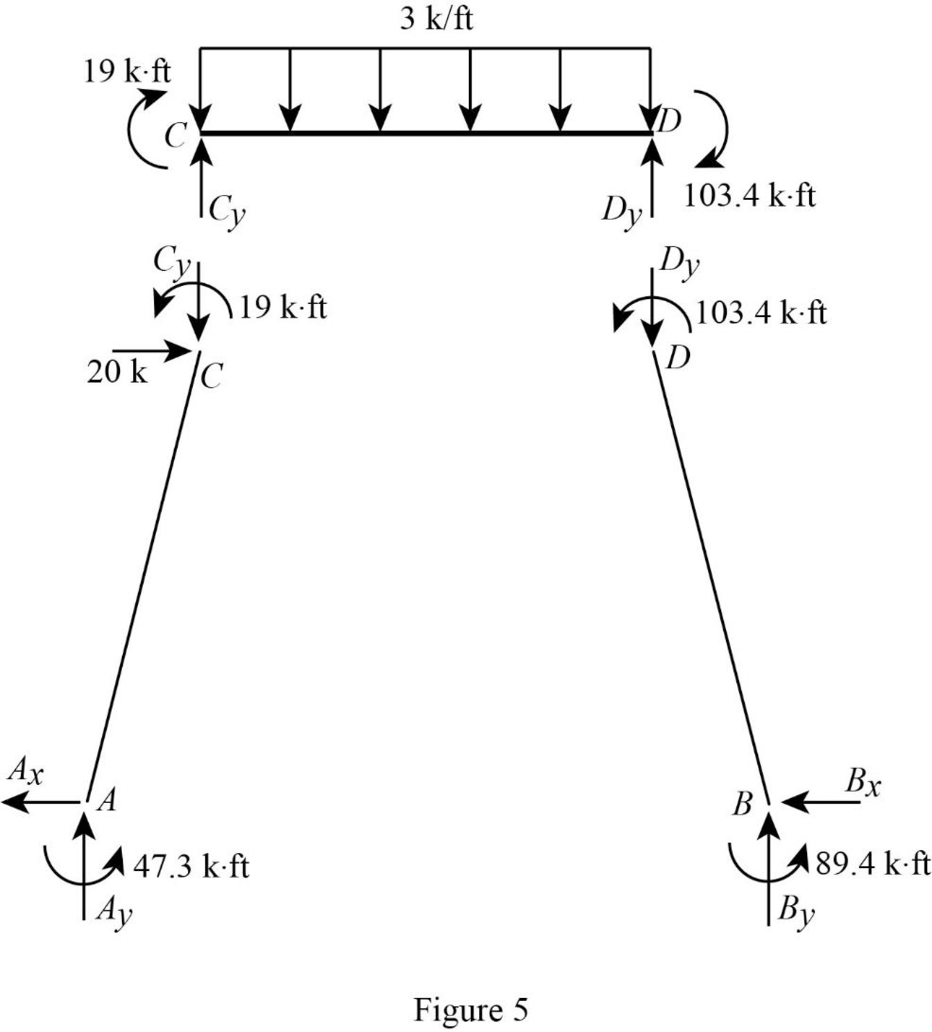
Consider the member CD.
Calculate the vertical reaction at the joint D by taking moment about point C.
Calculate the vertical reaction at joint C by resolving the vertical equilibrium.
Consider the member AC.
Calculate the vertical reaction at joint A by resolving the vertical equilibrium.
Calculate the horizontal reaction at the joint A by taking moment about point C.
Consider the member BD.
Calculate the vertical reaction at joint B by resolving the vertical equilibrium.
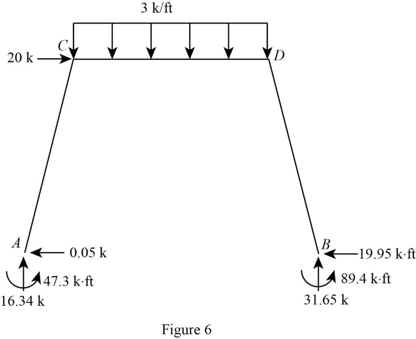
Consider the entire frame.
Calculate the horizontal reaction at the joint B by considering the horizontal equilibrium.
Show the reactions of the frame as in Figure 6.
Want to see more full solutions like this?
Chapter 15 Solutions
Structural Analysis, SI Edition


- 5. (20 Points) Consider a channel width change in the same 7-foot wide rectangular in Problem 4. The horizontal channel narrows as depicted below. The flow rate is 90 cfs, and the energy loss (headloss) through the transition is 0.05 feet. The water depth at the entrance to the transition is initially 4'. 1 b₁ TOTAL ENERGY LINE V² 129 У1 I b₂ TOP VIEW 2 PROFILE VIEW h₁ = 0.05 EGL Y₂ = ? a) b) c) 2 Determine the width, b₂ that will cause a choke at location 2. Determine the water depth at the downstream end of the channel transition (y₂) section if b₂ = 5 feet. Calculate the change in water level after the transition. Plot the specific energy diagram showing all key points. Provide printout in homework. d) What will occur if b₂ = = 1.5 ft.?arrow_forward4. (20 Points) A transition section has been proposed to raise the bed level a height Dz in a 7-foot wide rectangular channel. The design flow rate in the channel is 90 cfs, and the energy loss (headloss) through the transition is 0.05 feet. The water depth at the entrance to the transition section is initially 4 feet. b₁ = b = b2 1 TOTAL ENERGY LINE V² 129 Ут TOP VIEW 2 hloss = 0.05 " EGL Y₂ = ? PROFILE VIEW a) Determine the minimum bed level rise, Dz, which will choke the flow. b) If the step height, Dz = 1 ft, determine the water depth (y2) at the downstream end of the channel transition section. Calculate the amount the water level drops or rises over the step. c) Plot the specific energy diagram showing all key points. Provide printout in Bework. d) What will occur if Dz = 3.0 ft.?. Crest Front Viewarrow_forward1. (20 Points) Determine the critical depth in the trapezoidal drainage ditch shown below. The slope of the ditch is 0.0016, the side slopes are 1V:2.5H, the bottom width is b = 14', and the design discharge is 500 cfs. At this discharge the depth is y = 4.25'. Also, determine the flow regime and calculate the Froude number. Ye= ? Z barrow_forward
- 3. (20 Points) A broad crested weir, 10 feet high, will be constructed in a rectangular channel B feet wide. The weir crest extends a length of B = 120 feet between the banks with 2 - 4 foot wide, round nosed piers in the channel. The width of the weir crest is 8 feet. If H = 6', determine the design discharge for the weir.arrow_forwardParking Needs vs. Alternative Transportation Methods for presentation slides include images and graphsarrow_forwardPlease explain step by step and show formulararrow_forward
- Beam ABD is supported and loaded as shown. The cross-section of the beam is also shown. The modulus of elasticity of the beam is 200 GPa. 6.0 kN/m Cross-section: 330 mm 4.5 kN 8.0 kNm 40 mm 2.5 m 1.5 m 20 mm Set up the discontinuity moment function in terms of x. List all the appropriate boundary conditions. Determine the slope function in terms of x. Determine the deflection function in terms of x. Determine the support reactions. Determine the maximum deflection. 290 mmarrow_forwardDraw the Shear Force Diagram and Bending Moment Diagram for the beam shown in Fig.1. The beam is subjected to an UDL of w=65m. L=4.5m L1= 1.8m. Assume the support at C is pinned, and A and B are roller supports. E = 200GPa, I = 250x106 mm4.arrow_forwardCalculate the BMs (bending moments) at all the joints of the beam shown in Fig.1 using the Slope Deflection method. The beam is subjected to an UDL of w=65m. L=4.5m L1= 1.8m. Assume the support at C is pinned, and A and B are roller supports. E = 200GPa, I = 250x106 mm4.arrow_forward
