
Concept explainers
Find the member end moments and reaction for the frames.
Answer to Problem 30P
The end moments at the member AC
Explanation of Solution
Fixed end moment:
Formula to calculate the fixed moment for UDL is
Calculation:
Consider the flexural rigidity EI of the frame is constant.
Show the free body diagram of the entire frame as in Figure 1.
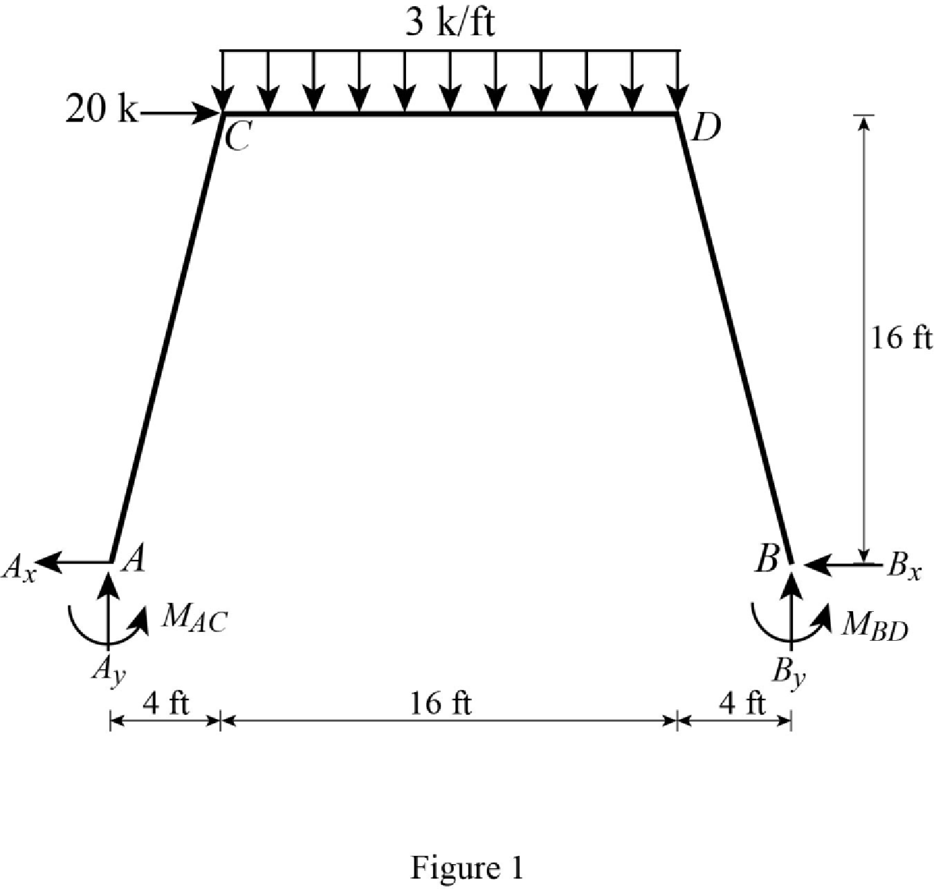
Refer Figure 1,
Calculate the fixed end moment for AC.
Calculate the fixed end moment for CA.
Calculate the fixed end moment for CD.
Calculate the fixed end moment for DC.
Calculate the fixed end moment for DB.
Calculate the fixed end moment for BD.
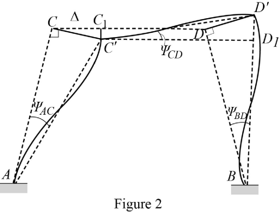
Chord rotations:
Show the free body diagram of the chord rotation of the frame as in Figure 2.
Calculate the length of AC by using Pythagoras theorem.
Calculate the length of BD by using Pythagoras theorem.
Calculate the chord rotation of the frame AC.
Calculate the chord rotation of the frame BD.
Calculate the chord rotation of the frame CD.
Calculate the slope deflection equation for the member AC.
Substitute 16.49 ft for L, 0 for
Calculate the slope deflection equation for the member CA.
Substitute 16.49 ft for L, 0 for
Calculate the slope deflection equation for the member CD.
Substitute 16 ft for L,
Calculate the slope deflection equation for the member DC.
Substitute 16 ft for L,
Calculate the slope deflection equation for the member DB.
Substitute 16.49 ft for L, 0 for
Calculate the slope deflection equation for the member BD.
Substitute 16.49 ft for L, 0 for
Write the equilibrium equation as below.
Substitute equation (2) and equation (3) in above equation.
Write the equilibrium equation as below.
Substitute equation (4) and equation (5) in above equation.
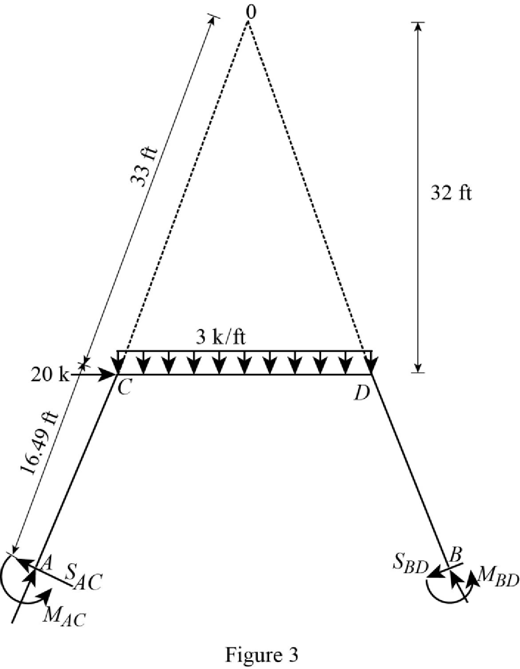
Show the free body diagram of the entire frame due to sway force as in Figure 3.
Show the free body diagram of the frame due to sway force as in Figure 4.
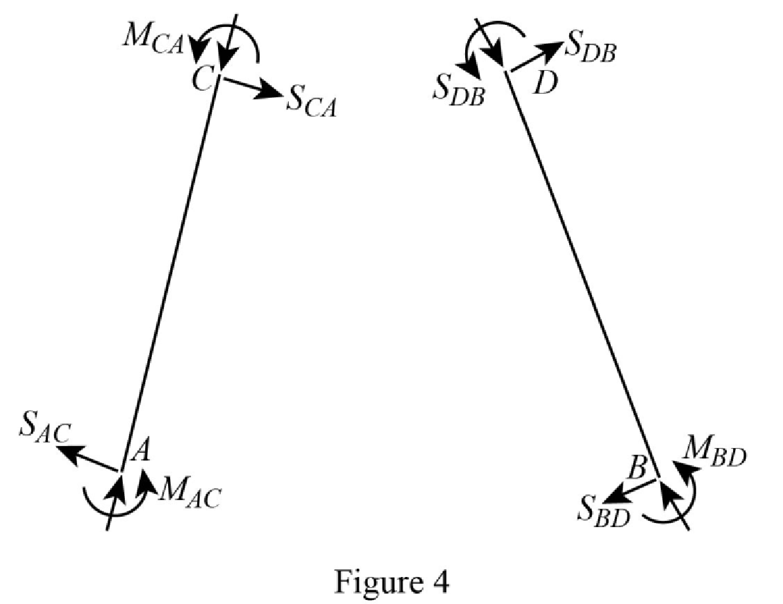
Calculate the horizontal reaction at the member AC due to sway force by taking moment about point A.
Calculate the horizontal reaction at the member BD due to sway force by taking moment about point B.
Calculate the reaction of the support C and support D due to sway force by taking the moment about O.
Substitute equation (1), equation (2), equation (5), and equation (6) in above equation.
Solve the equation (7), equation (8), and equation (9).
Calculate the moment about AC.
Substitute
Calculate the moment about CA.
Substitute
Calculate the moment about CD.
Substitute
Calculate the moment about DC.
Substitute
Calculate the moment about DB.
Substitute
Calculate the moment about BD.
Substitute
Show the section free body diagram of the member AC, CD and DB as in Figure 5.
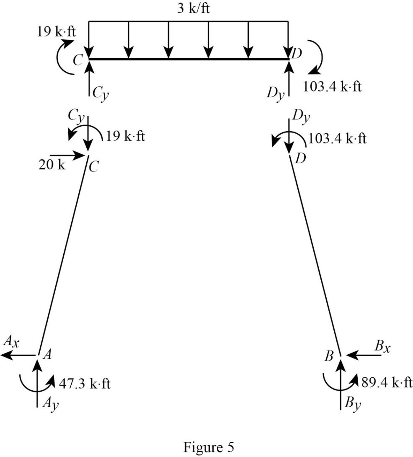
Consider the member CD.
Calculate the vertical reaction at the joint D by taking moment about point C.
Calculate the vertical reaction at joint C by resolving the vertical equilibrium.
Consider the member AC.
Calculate the vertical reaction at joint A by resolving the vertical equilibrium.
Calculate the horizontal reaction at the joint A by taking moment about point C.
Consider the member BD.
Calculate the vertical reaction at joint B by resolving the vertical equilibrium.
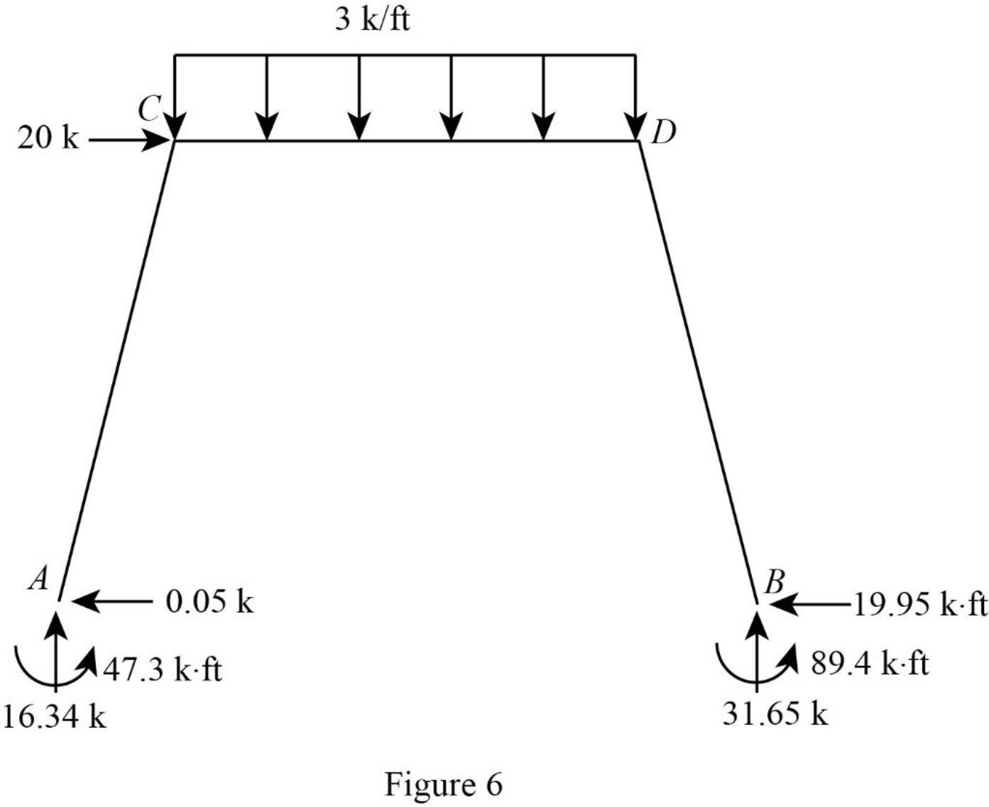
Consider the entire frame.
Calculate the horizontal reaction at the joint B by considering the horizontal equilibrium.
Show the reactions of the frame as in Figure 6.
Want to see more full solutions like this?
Chapter 15 Solutions
EBK STRUCTURAL ANALYSIS


- 1500 N A B 3500 N/m 1.2 m 3.6 m 1.2 m 1800 N Beam Cross-section: 4b T D b 25 mm 100 mm For beam ABCD with cross-section shown, design the beam by determining the following: Draw the shear and bending moment diagrams (show your detailed computations to get credit) The minimum dimension for b [mm], knowing that the allowable flexural stress and transverse shear stress are 10 MPa and 0.5 MPa, respectively.arrow_forwardCivil engineering quantiarrow_forwardPlease answer the questions in the picture. Thank you for your help. For part B use the Second Picture.arrow_forward
- Derive by deconvolution the six-hour unit hydrograph from the following data for a watershed having a drainage area of 216 km2 , assuming a constant rainfall abstraction rate and a constant baseflow of 20 m3 /s. Six-hour period 1 2 3 4 5 6 7 8 9 10 11 Rainfall (cm) 1.5 3.5 2.5 1.5 Streamflow (m3 /s) 26 71 174 226 173 99 49 33 26 22 21 Use the unit hydrograph developed to calculate the streamflow hydrographfrom a 12 hour-duration storm having 2 cm of rainfall excess in the first six hours and 3 cm inthe second six hours. Assume a constant baseflow rate of 30 m3/s.arrow_forwardPlease answer the following question in the picture. Thank you for your help.arrow_forwardGiven the unit hydrographic in the table, calculate the streamdlow hydrographic from a 12 hour duration story having 2cm of rainfall excess in the first six hours and 3cm in the second six hours. Assume a constant base flow rate of 30 m3/sarrow_forward
- Based on the following information, what is the owner’s equity? Current Assets: $162,000Current Liabilities: $91,000 Fixed Assets: $290,000 long-Term Debt: $140,000arrow_forwardPlease refer to the below figure. Use f y = 60,000 psi and f c′ = 3000 psi. Each web is reinforced with 2-#4 rebars in one layer. (a) Use the entire flange width as effective. Determine if the interior Double-Tee beam behaves as a T-beam or rectangular beam. (b) Determine the design moment strength of the section. Hint: You can collapse the two webs in a single web as discussed in class.arrow_forwardGrade is being established to the bottom of a footing that is 24” thick. The elevation of thetop of the footing is 102.33’. the elevation of the existing grade is 106.14’. the backsight of thesurveying instrument on a benchmark of 100.00’ is 6.78’. what is the correct reading for the rodat the bottom of the footing?arrow_forward
- 6.48 This "double" nozzle discharges water (p = 62.4 lbm/ft³) into the atmosphere at a rate of 16 cfs. If the nozzle is lying in a horizontal plane, what X-component of force acting through the flange bolts is required to hold the nozzle in place? Note: Assume irrotational flow, and assume the water speed in each jet to be the same. Jet A is 4 in. in diameter, jet B is 4.5 in. in diameter, and the pipe is 1.4 ft in diameter. A 30°F B Problem 6.48 Xxarrow_forward6-1 For the rectangular beam shown in Fig. P6-1, (a) Draw a shear-force diagram. (b) Assuming the beam is uncracked, show the direction of the principal tensile stresses at middepth at points A, B, and C. (c) Sketch, on a drawing of the beam, the inclined cracks that would develop at A, B, and C. 10 kips A B 1 kip/ft 7.5 ft Fig. P6-1 + 7.5 ft 6 ft 10 kipsarrow_forward6.85 A reducing pipe bend is held in place by a pedestal as shown. There are expansion joints at sections 1 and 2, so no force is transmitted through the pipe past these sections. The pressure at section 1 is 20 psig, and the rate of flow of water (p = 62.4 Ibm/ft³) is 2 cfs. Find the force and moment that must be applied at section 3 to hold the bend stationary. Assume the flow is irrotational, and neglect the influence of gravity. 6 in. diameter + 24 in. 24 in. (3 4 in. diameter Problem 6.85arrow_forward
