
Concept explainers
Find the reaction and plot the shear and bending moment diagram.
Answer to Problem 15P
The end moments at the member A
Explanation of Solution
Fixed end moment:
Formula to calculate the fixed moment for point load with equal length are
Formula to calculate the fixed moment for point load with unequal length are
Formula to calculate the fixed moment for UDL is
Formula to calculate the fixed moment for deflection is
Calculation:
Consider the flexural rigidity EI of the beam is constant.
Show the free body diagram of the entire beam as in Figure 1.
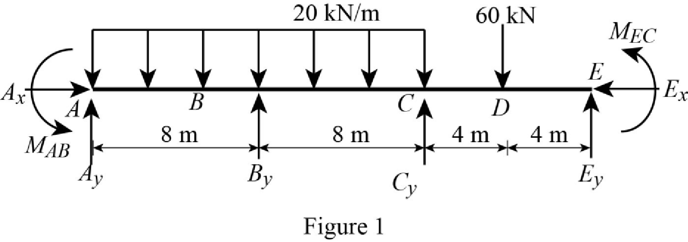
Refer Figure 1,
Calculate the fixed end moment for AB.
Calculate the fixed end moment for BA.
Calculate the fixed end moment for BC.
Calculate the fixed end moment for CB.
Calculate the fixed end moment for CE.
Calculate the fixed end moment for EC.
Chord rotations:
Show the free body diagram of the chord rotation of the beam as in Figure 2.

Calculate the chord rotation of the beam BC.
Calculate the chord rotation of the beam CE.
Calculate the slope deflection equation for the member AB.
Here,
Substitute
Calculate the slope deflection equation for the member BA.
Substitute
Calculate the slope deflection equation for the member BC.
Substitute
Calculate the slope deflection equation for the member CB.
Substitute
Calculate the slope deflection equation for the member CE.
Substitute
Calculate the slope deflection equation for the member EC.
Substitute
Write the equilibrium equation as below.
Substitute equation (2) and equation (3) in above equation.
Write the equilibrium equation as below.
Substitute equation (4) and equation (5) in above equation.
Solve the equation (7) and equation (8).
Calculate the moment about AB.
Substitute
Calculate the moment about BA.
Substitute
Calculate the moment about BC.
Substitute
Calculate the moment about CB.
Substitute
Calculate the moment about CE.
Substitute
Calculate the moment about EC.
Substitute
Consider the member AB of the beam:
Show the section free body diagram of the member AB, BC and CE as in Figure 3.

Calculate the vertical reaction at the left end of the joint B by taking moment about point A.
Calculate the horizontal reaction at point A by resolving the horizontal equilibrium.
Calculate the vertical reaction at point A by resolving the vertical equilibrium.
Consider the member BC of the beam:
Calculate the vertical reaction at the right end of the joint B by taking moment about point C.
Calculate the vertical reaction at the left end of joint C by resolving the vertical equilibrium.
Calculate the total reaction at point B.
Substitute
Calculate the vertical reaction at the right end of the joint C by taking moment about point E.
Calculate the horizontal reaction at point E by resolving the horizontal equilibrium.
Calculate the vertical reaction at point E by resolving the vertical equilibrium.
Calculate the total reaction at point C.
Substitute
Show the reactions of the beam in Figure 4.

Refer Figure 4,
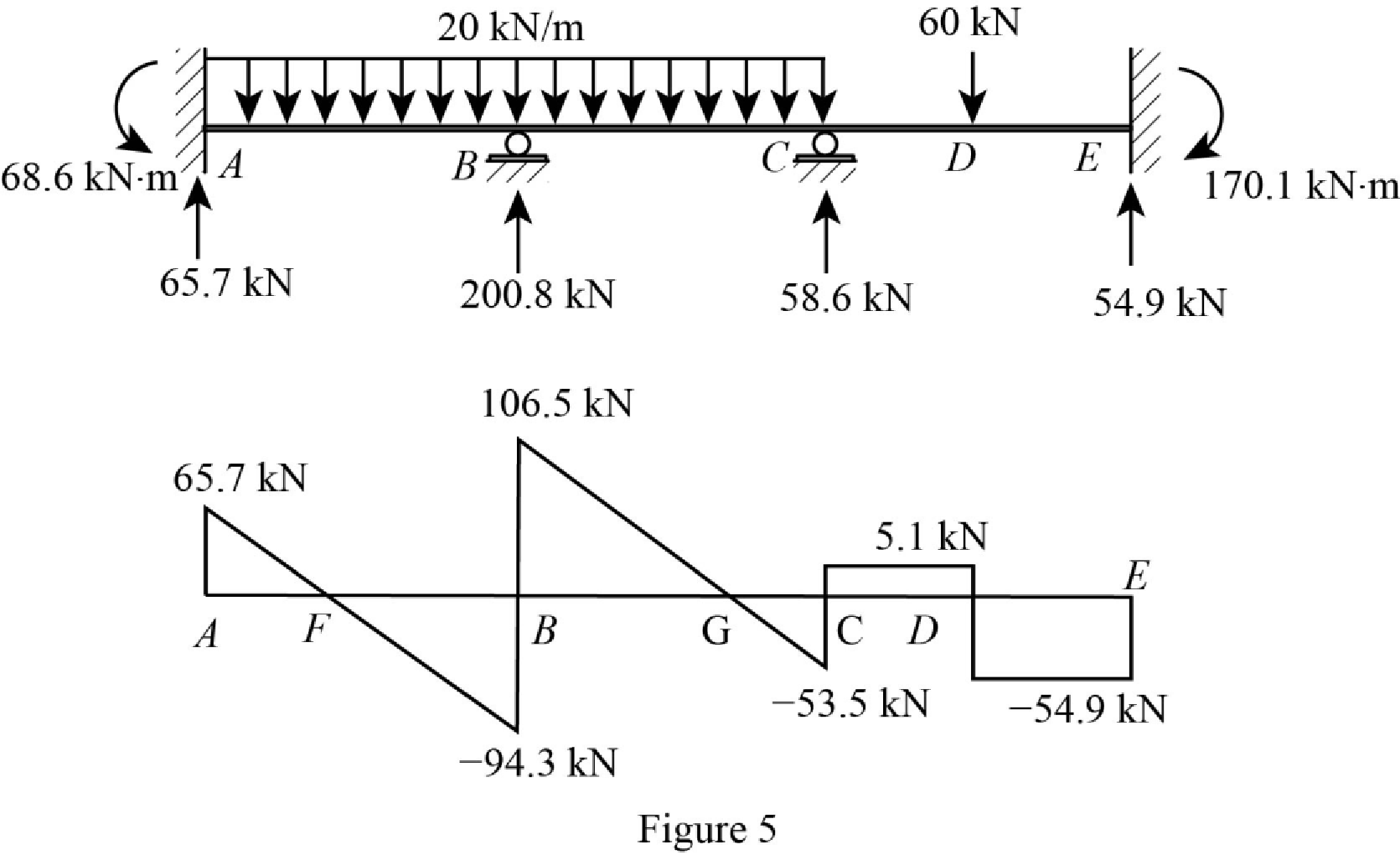
Shear diagram:
Point A:
Point B:
Point C:
Point E:
Plot the shear force diagram of the beam as in Figure 5.
Show the shear diagram of the section AB as in Figure 6.
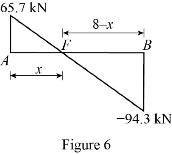
Use the similar triangle concept, to find the location of the maximum bending moment.
Show the shear diagram of the section BC as in Figure 7.
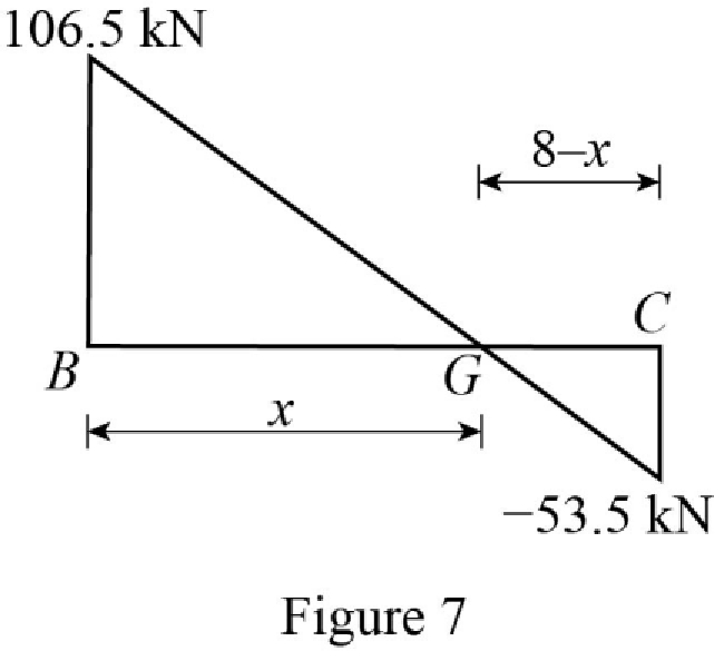
Use the similar triangle concept, to find the location of the maximum bending moment.
Refer Figure 4,
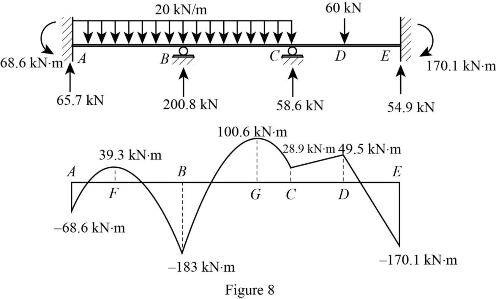
Bending moment diagram:
Point A:
Point F:
Point B:
Point G:
Point C:
Point D:
Point E:
Plot the bending moment diagram of the beam as in Figure 8.
Want to see more full solutions like this?
Chapter 15 Solutions
EBK STRUCTURAL ANALYSIS
- When using a work breakdown structure (WBS) for a project why it is necessary to break down activities?arrow_forwardAs shown in the figure below, a 1.5 m × 1.5 m footing is carrying a 400 kN load. P Depth (m) 0.0 1.0 2.0 Df Groundwater table (Yw = 9.81 kN/m³) 3.5 Yt = 16.5 kN/m³ E = 9,000 kPa Sandy soil Ysat 17.5 kN/m³ E = 15,000 kPa 6.0 Stiff Clay (OCR = 2) Bedrock Ysat 18.0 kN/m³ eo = 0.8 Cc = 0.15, Cr = 0.02 Eu =40,000 kPa (a) Estimate the immediate settlement beneath the center of the footing. Assuming that Poisson's ratios of sand and soft clay are 0.3 and 0.5, respectively. Use numerical integration approach. For the calculations, use layers (below the bottom of the footing) of thicknesses: 1 m; 1.5 m, and 2.5 m. (b) Determine the primary consolidation settlement beneath the center of the footing. (c) Redo Part (b) if OCR=1.1. Note: Use the 2:1 method to determine the stress increase below the footing. For parts (b) and (c), use the one-dimensional consolidation theory.arrow_forwardConsider the cross-sections illustrated in the next slides. Implement a cross-sectional analysis based on a layered discretisation of the cross- section as required at the following. 1) Develop the implementation of an analysis to estimate the nonlinear response of the composite steel-concrete section, of the reinforced concrete section and of the steel section shown in following slides (using material nonlinear models provided in the support files). Provide the details of the numerical implementation with clear explanations of all steps. Hint: the implementation can be done in Excel. 2) Discuss how the 3 cross-sections (shown in the next slides) compare to each other in terms of embodied carbon under the condition that the cross-sections possess the same nominal moment capacity (i.e. the peak moment achieved in the moment-curvature diagram). The discussion should include at least 2 sets of the sections (each set contains one composite section, one reinforced concrete section and one…arrow_forward
- Consider the following static route choice problem where 110 vehicles travel from point A to point B. The corresponding travel time (in minutes) of each link is as follows: t₁ = x1; t₂ = x2 + 20; t3x3 + 10; t₁ = 3×4 where Xi denotes the number of vehicles that choose link i. Find the number of vehicles that travel on each link when a. The user equilibrium condition (UE) is satisfied, where vehicles select the route with the minimum travel time; and b. The system optimum condition (SO) is satisfied, where the total travel time is minimised. C. Report the total delay savings when satisfying SO instead of UE. 2 B A 3 4arrow_forward= α₂+ Assume an origin is connected to a destination with two routes. Assume the travel time of each route has a linear relationship with the traffic flow on the route (t₁ = α₁ + b₁x₁ ; t₂ b2x2). Determine under what condition (e.g. a relationship among the parameters of the performance functions) tolling cannot reduce the total travel time of the two routes.arrow_forwardBeban berjalan pada konstruksi balok seperti pada gambar, tentukan besar gaya dalam yang terjadi dengan metode Garis Pengaruh. Gaya dalam berupa : Reaksi tumpuan RA dan RB, Gaya lintang max di titik C, Momen Maksimum di titik C A + Dimana: B D 10 5 m 5 m P1 = 12t P2 = 6t P3 = 18t q= 6 t/m 2 3 q = 6 t/m P1 P2 P3arrow_forward
- Consider the following static route choice problem where 110 vehicles travel from point A to point B. The corresponding travel time (in minutes) of each link is as follows: t₁ = x1 ; t₂ = = x2 + 20; t3 = x3 + 10; t₁ = 3x4 where Xi denotes the number of vehicles that choose link i. Find the number of vehicles that travel on each link when a. The user equilibrium condition (UE) is satisfied, where vehicles select the route with the minimum travel time; and b. The system optimum condition (SO) is satisfied, where the total travel time is minimised. C. Report the total delay savings when satisfying SO instead of UE. 2 A B 3 4arrow_forward= Assume an origin is connected to a destination with two routes. Assume the travel time of each route has a linear relationship with the traffic flow on the route (t₁ = α₁ + b₁×₁ ; t₂ b2x2). Determine under what condition (e.g. a relationship among the parameters of the performance functions) tolling cannot reduce the total travel time of the two routes. a2+arrow_forwardFor the soil system presented below, calculate and draw diagrams of distributions of the totaland effective stresses and pore water pressure. Assume an upward water flow with a velocity of0.000,001 cm/s.arrow_forward
- Refer to attached problem.arrow_forwardCalculate: a) effective stresses at points A and B before the placement of foundations 1 and 2, b)the increase of pressure at point A as a result of the placement of the circular foundation 1, c) theincrease of pressure at point B as a result of the placement of the strip foundation 2.arrow_forwardConsider the total head-loss in the system forthis flow is 18.56 ft (head-losses in first and second pipe are 13.83 ft and 4.73 ftrespectively). Please show numerical values for EGL/HGL at the beginning/end/intermediatechange point. (Point distribution: elevation determination 5 points, EGL, HGL lines 4points)arrow_forward
