
Concept explainers
Find the reaction and plot the shear and bending moment diagram.
Answer to Problem 15P
The end moments at the member A
Explanation of Solution
Fixed end moment:
Formula to calculate the fixed moment for point load with equal length are
Formula to calculate the fixed moment for point load with unequal length are
Formula to calculate the fixed moment for UDL is
Formula to calculate the fixed moment for deflection is
Calculation:
Consider the flexural rigidity EI of the beam is constant.
Show the free body diagram of the entire beam as in Figure 1.
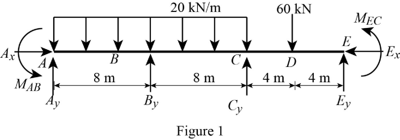
Refer Figure 1,
Calculate the fixed end moment for AB.
Calculate the fixed end moment for BA.
Calculate the fixed end moment for BC.
Calculate the fixed end moment for CB.
Calculate the fixed end moment for CE.
Calculate the fixed end moment for EC.
Chord rotations:
Show the free body diagram of the chord rotation of the beam as in Figure 2.
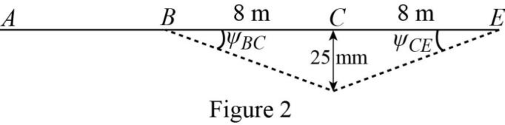
Calculate the chord rotation of the beam BC.
Calculate the chord rotation of the beam CE.
Calculate the slope deflection equation for the member AB.
Here,
Substitute
Calculate the slope deflection equation for the member BA.
Substitute
Calculate the slope deflection equation for the member BC.
Substitute
Calculate the slope deflection equation for the member CB.
Substitute
Calculate the slope deflection equation for the member CE.
Substitute
Calculate the slope deflection equation for the member EC.
Substitute
Write the equilibrium equation as below.
Substitute equation (2) and equation (3) in above equation.
Write the equilibrium equation as below.
Substitute equation (4) and equation (5) in above equation.
Solve the equation (7) and equation (8).
Calculate the moment about AB.
Substitute
Calculate the moment about BA.
Substitute
Calculate the moment about BC.
Substitute
Calculate the moment about CB.
Substitute
Calculate the moment about CE.
Substitute
Calculate the moment about EC.
Substitute
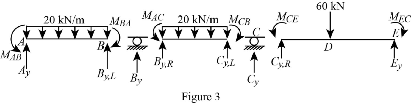
Consider the member AB of the beam:
Show the section free body diagram of the member AB, BC and CE as in Figure 3.
Calculate the vertical reaction at the left end of the joint B by taking moment about point A.
Calculate the horizontal reaction at point A by resolving the horizontal equilibrium.
Calculate the vertical reaction at point A by resolving the vertical equilibrium.
Consider the member BC of the beam:
Calculate the vertical reaction at the right end of the joint B by taking moment about point C.
Calculate the vertical reaction at the left end of joint C by resolving the vertical equilibrium.
Calculate the total reaction at point B.
Substitute
Calculate the vertical reaction at the right end of the joint C by taking moment about point E.
Calculate the horizontal reaction at point E by resolving the horizontal equilibrium.
Calculate the vertical reaction at point E by resolving the vertical equilibrium.
Calculate the total reaction at point C.
Substitute
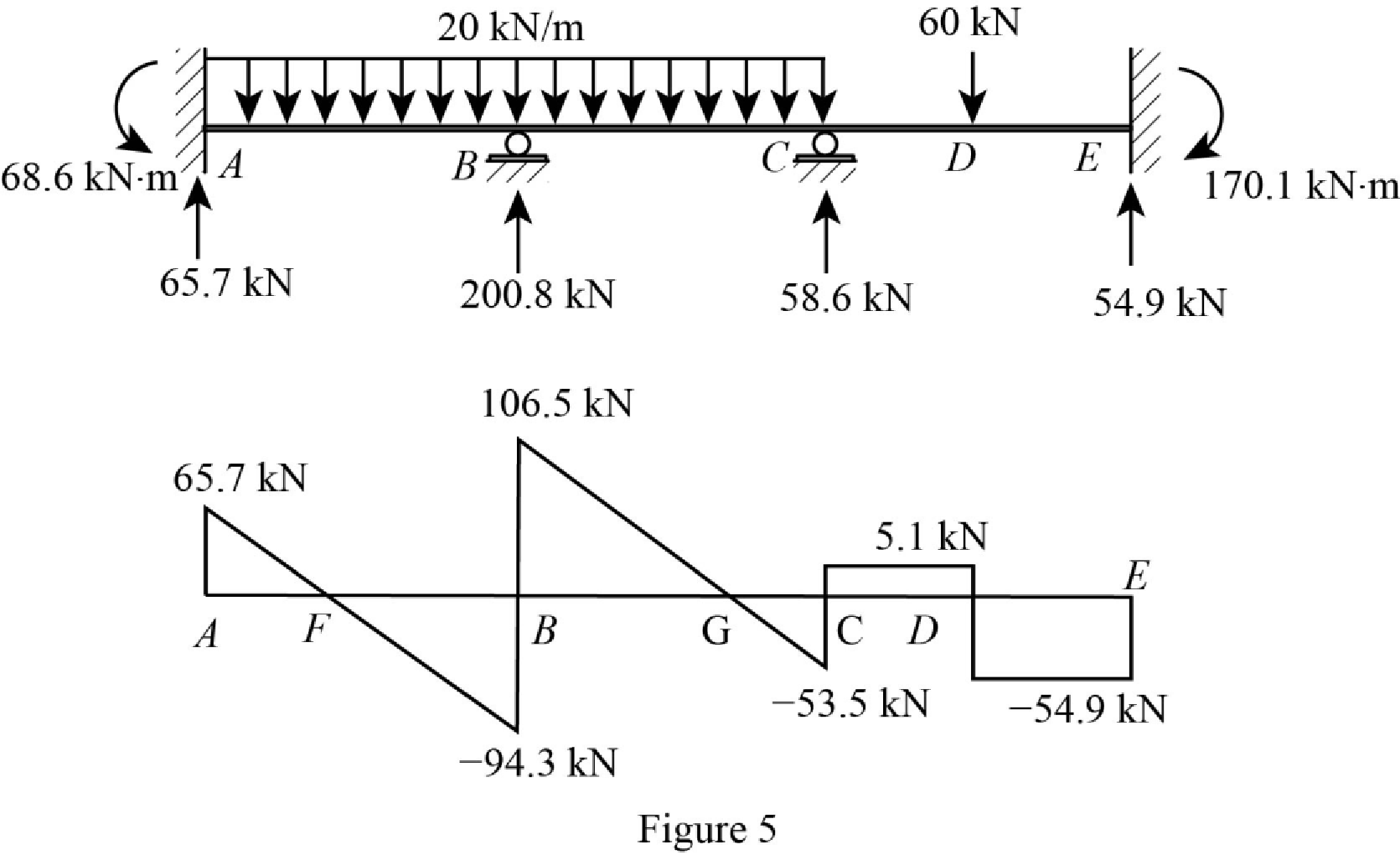
Show the reactions of the beam in Figure 4.
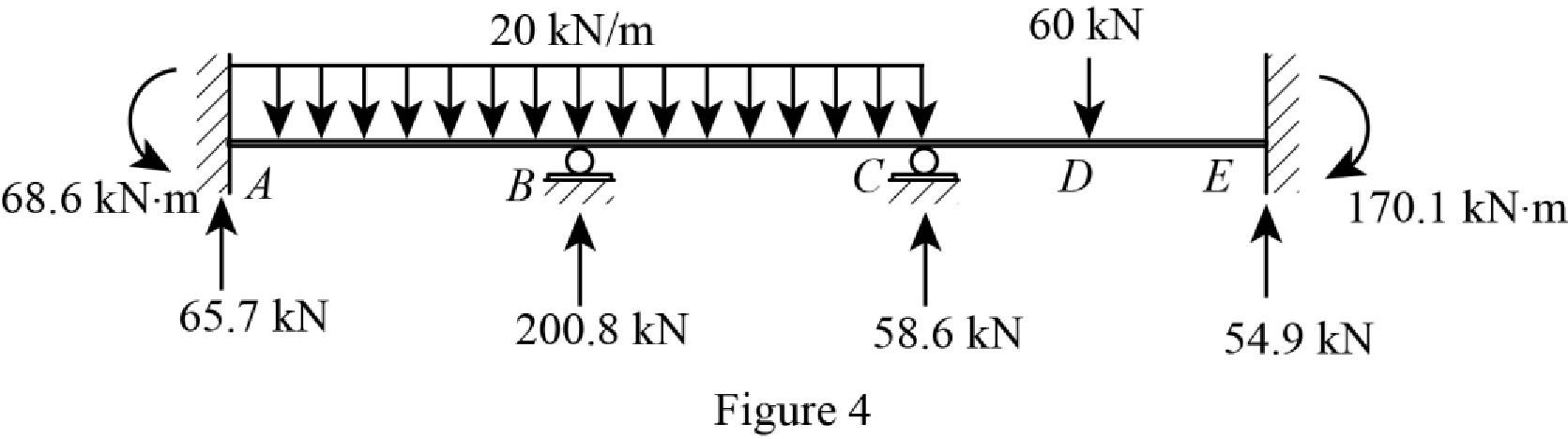
Refer Figure 4,
Shear diagram:
Point A:
Point B:
Point C:
Point E:
Plot the shear force diagram of the beam as in Figure 5.
Show the shear diagram of the section AB as in Figure 6.
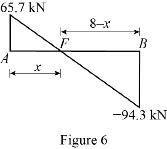
Use the similar triangle concept, to find the location of the maximum bending moment.
Show the shear diagram of the section BC as in Figure 7.
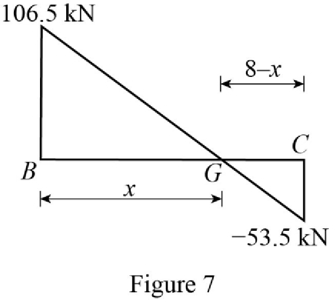
Use the similar triangle concept, to find the location of the maximum bending moment.
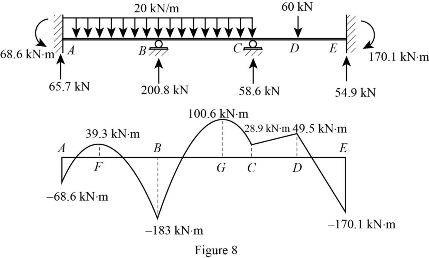
Refer Figure 4,
Bending moment diagram:
Point A:
Point F:
Point B:
Point G:
Point C:
Point D:
Point E:
Plot the bending moment diagram of the beam as in Figure 8.
Want to see more full solutions like this?
Chapter 15 Solutions
Structural Analysis, 5th Edition


- help me with this Question for revision purpose and as well with references The office building was built in year 2017 and has not obtained any Green Mark certification before. The office building is occupied by a single tenant/entity. The building management team had done an analysis of the building’s energy performance by extracting the data from the various systems. The current performance and findings of the systems are listed in Appendix A. The client is considering to have the building undergo retrofitting to improve the building’s energy performance. The objective is to achieve Green Mark Gold Plus under the new Green Mark 2021 framework. For part (a) below, you are to use Pathway 1: EUI for this. (a) As part of the feasibility exercise, you are to interpret the current performance of the existing building based on the data available (Refer to Appendix A). You should then organise and present to the client how does the current building relate to the Energy Efficiency Section of…arrow_forwardWhat are the advantages and disadvanages of using a bar chart in construction scheduling?arrow_forward1- Determine the area of the region enclosed by y = t sin(t), the x- axis, y-axis and x = Π 元-3arrow_forward
- The 4-story building shown below has a dead load D = 90 psf, floor live load, L = 110 psf. The roof and floors have the same D and L loads. The length of columns is 24 ft at the ground level and 12 ft for all other floors. The column ends are pins (Kx = Ky = 1.0) and Lx = Ly for all columns. (Use LFRD Method where applicable).1) Determine Pu on interior columns B2-4, B2-1, and side column C1-1 2) Use Table 4-1a (p. 4-12 to 4-24) in AISC to select the lightest W shapes for these columns 3) Use Table 4-4 (p. 4-68 to 4-83) in AISC to select lightest square HSS shape for the columnsarrow_forwardThe 4-story building shown below has a dead load D = 90 psf, floor live load, L = 110 psf. The roof and floors have the same D and L loads. The length of columns is 24 ft at the ground level and 12 ft for all other floors. The column ends are pins (Kx = Ky = 1.0) and Lx = Ly for all columns. Determine Pu on interior columns B2-4, B2-1, and side column C1-1 (Use LFRD where applicable).arrow_forwardProblems 5-1 Stead flow of steam enters a condenser with an enthalpy of 2400 kJ/kg and a velocity of 366 m/sec. the condensate leaves the condenser with an enthalpy of 162kJ/sec and a velocity of 6 m/sec what is the heat transferred to the cooling water per kg steam condensed. (-69198 kJ/kg) 5-2 An air compressor delivers 4.5 kg of air per minute at a pressure of 7 bar and a specific volume of 0.17 m³ /kg. Ambient conditions are pressure 1bar and specific volume 0.86 m³/kg. The initial and final internal energy values for the air are 28 kJ/kg and 110 kJ/kg respectively. Heat rejected to the cooling jacket is 76kJ/kg of air pumped. Neglecting changes in kinetic and potential energies, what is the shaft power required driving the compressor? (14.3kW)arrow_forward
