
Mechanics of Materials
10th Edition
ISBN: 9780134321158
Author: HIBBELER
Publisher: PEARSON
expand_more
expand_more
format_list_bulleted
Concept explainers
Videos
Textbook Question
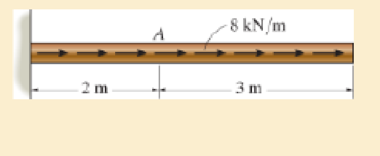
Chapter 1.5, Problem 1.4PP
Determine the internal normal force at section A if the rod is subjected to the external uniformally distributed loading along its length of 8 kN/m.
Expert Solution & Answer
Want to see the full answer?
Check out a sample textbook solution
Students have asked these similar questions
Sketch and desribe a balanced rudder and how it is suspended
A ship 140 m long and 18 m beam floats at a draught of9 m. The immersed cross-sectionai areas at equai intervais are 5,60, 116, 145, 152, 153, 153, 151, 142, 85 and 0 m2 respectively.Calculate:(a) displacement(b) block coefficient(c) midship section area coefficient(d) prismatic coefficient.
A steamer has waterplane area 1680m2 recorded in water with relative denisty 1.013. Displacement = 1200 t, calculate difference in draught in salwater reltive denisity 1.025.
Chapter 1 Solutions
Mechanics of Materials
Ch. 1.2 - In each case, explain how to find the resultant...Ch. 1.2 - Determine the resultant internal normal force,...Ch. 1.2 - Determine the resultant internal normal force,...Ch. 1.2 - Determine the resultant internal normal force,...Ch. 1.2 - Determine the resultant internal normal force,...Ch. 1.2 - Determine the resultant internal normal force,...Ch. 1.2 - Determine the resultant internal normal force,...Ch. 1.2 - The shaft is supported by a smooth thrust bearing...Ch. 1.2 - Determine the resultant internal normal and shear...Ch. 1.2 - Determine the resultant internal loadings acting...
Ch. 1.2 - The shaft is supported by a smooth thrust bearing...Ch. 1.2 - Determine the resultant internal loadings acting...Ch. 1.2 - Determine the resultant internal loadings on the...Ch. 1.2 - Determine the resultant internal loadings at cross...Ch. 1.2 - The beam supports the distributed load shown....Ch. 1.2 - The beam supports the distributed load shown....Ch. 1.2 - The boom DF of the jib crane and the column DE...Ch. 1.2 - Determine the resultant internal loadings acting...Ch. 1.2 - Determine the resultant internal loadings acting...Ch. 1.2 - The blade of the hacksaw is subjected to a...Ch. 1.2 - The blade of the hacksaw is subjected to a...Ch. 1.2 - The beam supports the triangular distributed load...Ch. 1.2 - The beam supports the distributed load shown....Ch. 1.2 - The shaft is supported at its ends by two bearings...Ch. 1.2 - The shaft is supported at its ends by two bearings...Ch. 1.2 - The hand crank that is used in a press has the...Ch. 1.2 - Determine the resultant internal loadings acting...Ch. 1.2 - Determine the resultant internal loadings acting...Ch. 1.2 - The metal stud punch is subjected to a force of...Ch. 1.2 - Determine the resultant internal loadings acting...Ch. 1.2 - Determine the resultant internal loadings acting...Ch. 1.2 - Determine the resultant internal loadings acting...Ch. 1.2 - Determine the resultant internal loadings acting...Ch. 1.2 - The pipe has a mass of 12 kg/m. If it is fixed to...Ch. 1.2 - If the drill bit jams when the brace is subjected...Ch. 1.2 - The curved rod AD of radius r has a weight per...Ch. 1.2 - A differential element taken from a curved bar is...Ch. 1.5 - In each case, determine the largest internal shear...Ch. 1.5 - Determine the largest internal normal force in the...Ch. 1.5 - Determine the internal normal force at section A...Ch. 1.5 - The lever is held to the fixed shaft using the pin...Ch. 1.5 - The single-V butt joint transmits the force of 5...Ch. 1.5 - The uniform beam is supported by two rods AB and...Ch. 1.5 - Determine the average normal stress on the cross...Ch. 1.5 - Determine the average normal stress on the cross...Ch. 1.5 - If the 600-kN force acts through the centroid of...Ch. 1.5 - Determine the average normal stress at points A,...Ch. 1.5 - Determine the average normal stress in rod AB if...Ch. 1.5 - The supporting wheel on a scaffold is held in...Ch. 1.5 - Determine the largest intensity w of the uniform...Ch. 1.5 - The bar has a cross-sectional area A and is...Ch. 1.5 - The small block has a thickness of 0.5 in. If the...Ch. 1.5 - If the material fails when the average normal...Ch. 1.5 - If the block is subjected to a centrally applied...Ch. 1.5 - The plate has a width of 0.5 m. If the stress...Ch. 1.5 - The board is subjected to a tensile force of 200...Ch. 1.5 - The boom has a uniform weight of 600 lb and is...Ch. 1.5 - Determine the average normal stress in each of the...Ch. 1.5 - If the average normal stress in each of the...Ch. 1.5 - Determine the maximum average shear stress in pin...Ch. 1.5 - If P=5 kN, determine the average shear stress in...Ch. 1.5 - Determine the maximum magnitude P of the loads the...Ch. 1.5 - The column is made of concrete having a density of...Ch. 1.5 - The beam is supported by two rods AB and CD that...Ch. 1.5 - The beam is supported by two rods AB and CD that...Ch. 1.5 - If P = 15 kN, determine the average shear stress...Ch. 1.5 - The railcar docklight is supported by the...Ch. 1.5 - The plastic block is subjected to an axial...Ch. 1.5 - The two steel members are joined together using a...Ch. 1.5 - The bar has a cross-sectional area of 400(106) m2....Ch. 1.5 - The bar has a cross-sectional area of 400(106) m2....Ch. 1.5 - The two members used in the construction of an...Ch. 1.5 - The 2-Mg concrete pipe has a center of mass at...Ch. 1.5 - The 2-Mg concrete pipe has a center of mass at...Ch. 1.5 - The pier is made of material having a specific...Ch. 1.5 - Rods AB and BC have diameters of 4 mm and 6 mm,...Ch. 1.5 - The uniform bar, having a cross-sectional area of...Ch. 1.5 - The bar has a cross-sectional area of 400(106) m2....Ch. 1.5 - The bar has a cross-sectional area of 400(106) m2....Ch. 1.5 - The prismatic bar has a cross-sectional area A. If...Ch. 1.5 - The prismatic bar has a cross-sectional area A. If...Ch. 1.5 - The bars of the truss each have a cross-sectional...Ch. 1.5 - The bars of the truss each have a cross-sectional...Ch. 1.5 - Determine the largest load P that can be applied...Ch. 1.5 - Determine the greatest constant angular velocity ...Ch. 1.5 - The radius of the pedestal is defined by r =...Ch. 1.7 - Rods AC and BC are used to suspend the 200-kg...Ch. 1.7 - If it is subjected to double shear, determine the...Ch. 1.7 - Determine the maximum average shear stress...Ch. 1.7 - If each of the three nails has a diameter of 4 mm...Ch. 1.7 - The strut is glued to the horizontal member at...Ch. 1.7 - Determine the maximum average shear stress...Ch. 1.7 - If the eyebolt is made of a material having a...Ch. 1.7 - If the bar assembly is made of a material having a...Ch. 1.7 - Determine the maximum force P that can be applied...Ch. 1.7 - The pin is made of a material having a failure...Ch. 1.7 - If the bolt head and the supporting bracket are...Ch. 1.7 - Six nails are used to hold the hanger at A against...Ch. 1.7 - If A and B are both made of wood and are 38 in....Ch. 1.7 - Prob. 1.70PCh. 1.7 - The connection is made using a bolt and nut and...Ch. 1.7 - The tension member is fastened together using two...Ch. 1.7 - The steel swivel bushing in the elevator control...Ch. 1.7 - The spring mechanism is used as a shock absorber...Ch. 1.7 - Determine the size of square bearing plates A and...Ch. 1.7 - Determine the maximum load P that can be applied...Ch. 1.7 - Determine the required diameter of the pins at A...Ch. 1.7 - If the allowable tensile stress for wires AB and...Ch. 1.7 - If the allowable tensile stress for wires AB and...Ch. 1.7 - The cotter is used to hold the two rods together....Ch. 1.7 - Determine the required diameter of the pins at A...Ch. 1.7 - The steel pipe is supported on the circular base...Ch. 1.7 - The boom is supported by the winch cable that has...Ch. 1.7 - The boom is supported by the winch cable that has...Ch. 1.7 - The assembly consists of three disks A, B, and C...Ch. 1.7 - The two aluminum rods support the vertical force...Ch. 1.7 - The two aluminum rods AB and AC have diameters of...Ch. 1.7 - Determine the required minimum thickness t of...Ch. 1.7 - Determine the maximum allowable load P that can be...Ch. 1.7 - The compound wooden beam is connected together by...Ch. 1.7 - The hanger is supported using the rectangular pin....Ch. 1.7 - The hanger is supported using the rectangular pin....Ch. 1.7 - The rods AB and CD are made of steel. Determine...Ch. 1.7 - The aluminum bracket A is used to support the...Ch. 1.7 - If the allowable tensile stress for the bar is...Ch. 1.7 - The bar is connected to the support using a pin...Ch. 1 - The beam AB is pin supported at A and supported by...Ch. 1 - The long bolt passes through the 30-mm-thick...Ch. 1 - Determine the required thickness of member BC to...Ch. 1 - The circular punch B exerts a force of 2 kN on the...Ch. 1 - Determine the average punching shear stress the...Ch. 1 - The 150 mm by 150 mm block of aluminum supports a...Ch. 1 - The yoke-and-rod connection is subjected to a...Ch. 1 - The cable has a specific weight (weight/volume)...
Knowledge Booster


Learn more about
Need a deep-dive on the concept behind this application? Look no further. Learn more about this topic, mechanical-engineering and related others by exploring similar questions and additional content below.Similar questions
- relative velocity 11.72 m/s is correct, need help finding the angle pleasearrow_forwardDetermine the distance between the two automobiles 2 s after A has passed through the intersection.arrow_forwardA box barge 65 m long and 12 m wide floats at a draught of5.5 m in sea water. Calculate:(a) the displacement of the barge,(b) its draught in fresh waterarrow_forward
- what is the angle of the velocity of block B? velocity is 7.46 in/s Determine the acceleration and angle of block B. (Round the acceleration value to three decimal places.)arrow_forwardDetermine the relative velocity of B with respect to A.arrow_forwardGenerate the kinematic diagram of the following mechanism. Then, draw their graphs and calculate their degrees of freedom (DoF) using Gruebler's formula.arrow_forward
- An elastic bar of length L = 1m and cross section A = 1cm2 spins with angular velocity ω about an axis, as shown in the figure below. The radial acceleration at a generic point x along the bar is a(x) = ω2x, where ω= 100rad/s is the angular velocity. The bar is pinned on the rotation axis at x = 0. A mass M = 1kg is attached to the right end of the bar. Due to the radial acceleration, the bar stretches along x with displacement function u(x). The displacement u(x) solves the BVP (strong form) sketched below: d dx (σ(x)) + ρa(x) = 0 PDE σ(x) = E du dx Hooke’s law (1) u(0) =?? essential BC σ(L) =?? natural BC where σ(x) is the axial stress in the rod, ρ= 2700kg /m3 is the mass density, and E = 70GPa is the Young’s modulus 1. Define appropriate BCs for the strong BVP 2. Find the solution of the strong BVP analytically 3. Derive the weak form of the BVP.arrow_forwardGruebler's formula for the following mechanism?arrow_forwardw/I - | العنوان I need a detailed drawing with explanation SOLL эт 4 حكا The guide vane angle of a reaction turbine (Francis type make 20° with the tangent. The moving blade angle at entry is 120°. The external diameter of runner is 450 mm and the internal diameter is 300 mm. Runner width at entry is 62.5mm and at exit 100mm. Calculate the blade angle at exit for radial discharge. 96252 -20125 750 ×2.01arrow_forward
- Compressor Selection: (Q1) While a manufacturing cell is running, the calculated flow rate of air into a compressor is 40 SCFM. Which compressor from this list should be selected? A. A compressor that uses 80 SCFM B. A compressor that uses 40 SCFM C. A compressor that delivers 80 SCFM D. A compressor that delivers 40 SCFMarrow_forwardSCFM Calculation: (Q1) A pneumatic system running a manufacturing cell works on 80 psi and requires a flow rate of 10 CFM to operate. A compressor must be selected to run the cell. Calculate the amount of air going into the compressor to run this cell. (Hint: This will be in SCFM) Accurate to two decimals. Do not write the unit.arrow_forward: +00 العنوان >scóny : + 개 العنوان I need a actanicu urawing wit д い Ants nation Taxi pu +9635. The guide vane angle of a reaction turbine (Francis type make 20° with the tangent. The moving blade angle at entry is 120°. The external diameter of runner is 450 mm and the internal diameter is 300 mm. Runner width at entry is 62.5mm and at exit 100mm. Calculate the blade angle t exit for radial discharge. ۲/۱ = 44 985arrow_forward
arrow_back_ios
SEE MORE QUESTIONS
arrow_forward_ios
Recommended textbooks for you
 Elements Of ElectromagneticsMechanical EngineeringISBN:9780190698614Author:Sadiku, Matthew N. O.Publisher:Oxford University Press
 Mechanics of Materials (10th Edition)Mechanical EngineeringISBN:9780134319650Author:Russell C. HibbelerPublisher:PEARSON
 Thermodynamics: An Engineering ApproachMechanical EngineeringISBN:9781259822674Author:Yunus A. Cengel Dr., Michael A. BolesPublisher:McGraw-Hill Education
 Control Systems EngineeringMechanical EngineeringISBN:9781118170519Author:Norman S. NisePublisher:WILEY
 Mechanics of Materials (MindTap Course List)Mechanical EngineeringISBN:9781337093347Author:Barry J. Goodno, James M. GerePublisher:Cengage Learning
 Engineering Mechanics: StaticsMechanical EngineeringISBN:9781118807330Author:James L. Meriam, L. G. Kraige, J. N. BoltonPublisher:WILEY
Elements Of Electromagnetics
Mechanical Engineering
ISBN:9780190698614
Author:Sadiku, Matthew N. O.
Publisher:Oxford University Press
Mechanics of Materials (10th Edition)
Mechanical Engineering
ISBN:9780134319650
Author:Russell C. Hibbeler
Publisher:PEARSON
Thermodynamics: An Engineering Approach
Mechanical Engineering
ISBN:9781259822674
Author:Yunus A. Cengel Dr., Michael A. Boles
Publisher:McGraw-Hill Education
Control Systems Engineering
Mechanical Engineering
ISBN:9781118170519
Author:Norman S. Nise
Publisher:WILEY
Mechanics of Materials (MindTap Course List)
Mechanical Engineering
ISBN:9781337093347
Author:Barry J. Goodno, James M. Gere
Publisher:Cengage Learning
Engineering Mechanics: Statics
Mechanical Engineering
ISBN:9781118807330
Author:James L. Meriam, L. G. Kraige, J. N. Bolton
Publisher:WILEY
Types Of loads - Engineering Mechanics | Abhishek Explained; Author: Prime Course;https://www.youtube.com/watch?v=4JVoL9wb5yM;License: Standard YouTube License, CC-BY