
Mechanics of Materials Plus Mastering Engineering with Pearson eText - Access Card Package (10th Edition)
10th Edition
ISBN: 9780134518121
Author: Russell C. Hibbeler
Publisher: PEARSON
expand_more
expand_more
format_list_bulleted
Concept explainers
Videos
Textbook Question
Chapter 13.3, Problem 13.29P
The linkage is made using two A-36 steel rods, each having a circular cross section. Determine the diameter of each rod to the nearest
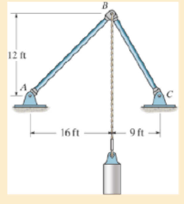
Prob. 13−29
Expert Solution & Answer
Want to see the full answer?
Check out a sample textbook solution
Students have asked these similar questions
Calculate the mean piston speed (in mph) for a Formula 1 engine running at 14,750 rpm with a bore of 80mm and a stroke of 53mm. Estimate the average acceleration imparted on the piston as it moves from TDC to 90 degrees ATDC
Calculate the compression ratio of an engine with a stroke of 4.2inches a bore of 4.5 inches and a clearance volume of 6.15 cubic inches. Discuss whether or not this is a realistic compression ratio for a street engine and what octane rating of fuel it would need to run correctly
Draw the free-body diagram for the pinned assembly shown. Find the magnitude of the forces
acting on each member of the assembly.
1500 N
1500 N
C
45°
45°
45°
45°
1000 mm
Chapter 13 Solutions
Mechanics of Materials Plus Mastering Engineering with Pearson eText - Access Card Package (10th Edition)
Ch. 13.3 - A 50-in long steel rod has a diameter of 1 in....Ch. 13.3 - A 12-ft wooden rectangular column has the...Ch. 13.3 - The A992 steel column can be considered pinned at...Ch. 13.3 - A steel pipe is fixed supported at its ends. If it...Ch. 13.3 - Determine the maximum force P that can be...Ch. 13.3 - The A992 steel rod BC has a diameter of 50 mm and...Ch. 13.3 - Determine the critical buckling load for the...Ch. 13.3 - The column consists of a rigid member that is...Ch. 13.3 - The aircraft link is made from an A992 steel rod....Ch. 13.3 - Rigid bars AB and BC are pin connected at B. If...
Ch. 13.3 - A 2014-T6 aluminium alloy column has a length of 6...Ch. 13.3 - Solve Prob. 13-5 if the column is pinned at its...Ch. 13.3 - The W12 50 is made of A992 steel and is used as a...Ch. 13.3 - The W12 50 is made of A992 steel and is used as a...Ch. 13.3 - A steel column has a length of 9 m and is fixed at...Ch. 13.3 - A steel column has a length of 9 m and is pinned...Ch. 13.3 - The A992 steel angle has a cross-sectional area of...Ch. 13.3 - The 50-mm-diameter C86100 bronze rod is fixed...Ch. 13.3 - Determine the maximum load P the frame can support...Ch. 13.3 - The W8 67 wide-flange A-36 steel column can be...Ch. 13.3 - Prob. 13.15PCh. 13.3 - Prob. 13.16PCh. 13.3 - The 10-ft wooden rectangular column has the...Ch. 13.3 - The 10-fl wooden column has the dimensions shown....Ch. 13.3 - Determine the maximum force P that can be applied...Ch. 13.3 - The A-36 steel pipe has an outer diameter of 2 in....Ch. 13.3 - The A-36 steel pipe has an outer diameter of 2 in....Ch. 13.3 - The deck is supported by the two 40-mm-square...Ch. 13.3 - The deck is supported by the two 40-mm-square...Ch. 13.3 - The beam is supported by the three pin-connected...Ch. 13.3 - The W14 30 A992 steel column is assumed pinned at...Ch. 13.3 - The A992 steel bar AB has a square cross section....Ch. 13.3 - The linkage is made using two A992 steel rods,...Ch. 13.3 - The linkage is made using two A992 steel rods,...Ch. 13.3 - The linkage is made using two A-36 steel rods,...Ch. 13.3 - The linkage is made using two A-36 steel rods,...Ch. 13.3 - The steel bar AB has a rectangular cross section....Ch. 13.3 - Determine if the frame can support a load of P =...Ch. 13.3 - Determine the maximum allowable load P that can be...Ch. 13.3 - Prob. 13.34PCh. 13.3 - Prob. 13.35PCh. 13.3 - The members of the truss are assumed to be pin...Ch. 13.3 - Solve Prob. 1336 for member AB, which has a radius...Ch. 13.3 - The truss is made from A992 steel bars, each of...Ch. 13.3 - The truss is made from A992 steel bars, each of...Ch. 13.3 - Prob. 13.40PCh. 13.3 - The ideal column has a weight w (force/length) and...Ch. 13.3 - The ideal column is subjected to the force F at...Ch. 13.3 - The column with constant El has the end...Ch. 13.3 - Consider an ideal column as in Fig.13-10 c, having...Ch. 13.3 - Consider an ideal column as in Fig. 13-10d, having...Ch. 13.5 - The wood column is fixed at its base and free at...Ch. 13.5 - The W10 12 structural A-36 steel column is used...Ch. 13.5 - The W10 12 structural A-36 steel column is used...Ch. 13.5 - The aluminium column is fixed at the bottom and...Ch. 13.5 - Prob. 13.50PCh. 13.5 - Prob. 13.51PCh. 13.5 - The aluminum rod is fixed at its base and free and...Ch. 13.5 - Assume that the wood column is pin connected at...Ch. 13.5 - Prob. 13.54PCh. 13.5 - The wood column is pinned at its base and top. If...Ch. 13.5 - Prob. 13.56PCh. 13.5 - Prob. 13.57PCh. 13.5 - Prob. 13.58PCh. 13.5 - Prob. 13.59PCh. 13.5 - The wood column is pinned at its base and top. If...Ch. 13.5 - The brass rod is fixed at one end and free at the...Ch. 13.5 - The brass rod is fixed at one end and free at the...Ch. 13.5 - Prob. 13.63PCh. 13.5 - A W14 30 structural A-36 steel column is pin...Ch. 13.5 - Prob. 13.65PCh. 13.5 - The 6061-T6 aluminum alloy solid shaft is fixed at...Ch. 13.5 - The 6061-T6 aluminum alloy solid shaft is fixed at...Ch. 13.5 - The W14 53 structural A992 steel column is fixed...Ch. 13.5 - The W14 53 column is fixed at its base and free...Ch. 13.5 - Prob. 13.70PCh. 13.5 - The stress-strain diagram for a material can be...Ch. 13.5 - The stress-strain diagram for a material can be...Ch. 13.5 - The stress-strain diagram for the material of a...Ch. 13.5 - Construct the buckling curve, P/A versus L/ r, for...Ch. 13.5 - The stress-strain diagram of the material can be...Ch. 13.5 - The stress-strain diagram of the material can be...Ch. 13.5 - Prob. 13.77PCh. 13.6 - Determine the largest length of a W10 12...Ch. 13.6 - Using the AISC equations, select from AppendixB...Ch. 13.6 - Take Y = 50 ksi.Ch. 13.6 - Determine the longest length of a W8 31...Ch. 13.6 - Using the AISC equations, select from AppendixB...Ch. 13.6 - Prob. 13.83PCh. 13.6 - Using the AISC equations, select from AppendixB...Ch. 13.6 - Prob. 13.85PCh. 13.6 - Prob. 13.86PCh. 13.6 - Prob. 13.87PCh. 13.6 - Prob. 13.88PCh. 13.6 - Using the AISC equations, check if a column having...Ch. 13.6 - The beam and column arrangement is used in a...Ch. 13.6 - Prob. 13.91PCh. 13.6 - Prob. 13.92PCh. 13.6 - The 1-in.-diameter rod is used to support an axial...Ch. 13.6 - The 1-in.-diameter rod is used to support an axial...Ch. 13.6 - Prob. 13.95PCh. 13.6 - Prob. 13.96PCh. 13.6 - Prob. 13.97PCh. 13.6 - Prob. 13.98PCh. 13.6 - The tube is 0.25 in. thick, is made of 2014-T6...Ch. 13.6 - Prob. 13.100PCh. 13.6 - A rectangular wooden column has the cross section...Ch. 13.6 - Prob. 13.102PCh. 13.6 - Prob. 13.103PCh. 13.6 - The bar is made of aluminum alloy 2014-T6....Ch. 13.6 - Prob. 13.105PCh. 13.6 - Prob. 13.106PCh. 13.7 - The W8 15 wide-flange A-36 steel column is...Ch. 13.7 - Solve Prob.13-107 if the column is fixed at its...Ch. 13.7 - Prob. 13.109PCh. 13.7 - Prob. 13.110PCh. 13.7 - The W8 15 wide-flange A992 steel column is fixed...Ch. 13.7 - The W8 15 wide-flange A992 steel column is fixed...Ch. 13.7 - The W12 22 wide-flange A-36 steel column is fixed...Ch. 13.7 - Prob. 13.114PCh. 13.7 - Prob. 13.115PCh. 13.7 - Prob. 13.116PCh. 13.7 - A 20-ft-long column is made of aluminum alloy...Ch. 13.7 - A 20-ft-long column is made of aluminum alloy...Ch. 13.7 - The 2014-T6 aluminum hollow column is fixed at its...Ch. 13.7 - The 2014-T6 aluminum hollow column is fixed at its...Ch. 13.7 - Prob. 13.121PCh. 13.7 - Prob. 13.122PCh. 13.7 - Prob. 13.123PCh. 13.7 - Prob. 13.124PCh. 13.7 - The 10-in.-diameter utility pole supports the...Ch. 13.7 - Using the NFPA equations of Sec 13.6. and Eq....Ch. 13.7 - Prob. 13.127PCh. 13 - The wood column has a thickness of 4 in. and a...Ch. 13 - The wood column has a thickness of 4 in. and a...Ch. 13 - A steel column has a length of 5 m and is free at...Ch. 13 - The square structural A992 steel tubing has outer...Ch. 13 - If the A-36 steel solid circular rod BD has a...Ch. 13 - If P = 15 kip, determine the required minimum...Ch. 13 - The steel pipe is fixed supported at its ends. If...Ch. 13 - The W200 46 wide-flange A992-steel column can be...Ch. 13 - The wide-flange A992 steel column has the cross...Ch. 13 - The wide-flange A992 steel column has the cross...
Knowledge Booster


Learn more about
Need a deep-dive on the concept behind this application? Look no further. Learn more about this topic, mechanical-engineering and related others by exploring similar questions and additional content below.Similar questions
- An elastic bar of length L spins with angular velocity ω about an axis, as shown in the figure below. The radial acceleration at a generic point x along the bar is a(x) = ω 2 x. Due to this radial acceleration, the bar stretches along x with displacement function u(x). The displacement u(x) is governed by the following equations: ( d dx (σ(x)) + ρa(x) = 0 PDE σ(x) = E du dx Hooke’s law (1) where σ(x) is the axial stress in the rod, ρ is the mass density, and E is the (constant) Young’s modulus. The bar is pinned on the rotation axis at x = 0, and it is free at x = L. Determine:1. Appropriate BCs for this physical problem.2. The displacement function u(x).3. The stress function σ(x).arrow_forwardWith reference to the given figure: a) Draw a free-body diagram of the structure supporting the pulley. b) Draw shear and bending moment diagrams for both the vertical and horizontal portions of the structure. 48 in. 100 lb 12 in. Cable 27 in. 12-in. pulley radius 100 lb Cablearrow_forwardConsider a standard piston engine . Draw a free body diagram of the piston. Then:a) For an A SI engine with a 100 mm bore at an instantaneous cylinder pressure of 42 bar i. Calculate the level of the combustion gas loading force on the wrist pin in kN. b) Repeat this calculationfor a forced-induction Diesel engine with a 145 mm boreat a cylinder pressure of 115 bararrow_forward
- A punch press with flywheel adequate to minimize speed fluctuation produces 120 punching strokes per minute, each providing an average force of 2000 N over a stroke of 50 mm. The press is driven through a gear reducer by a shaft rotating 200 rpm. Overall efficiency is 80%. a) What power (W) is transmitted through the shaft? b) What average torque is applied to the shaft?arrow_forward1.58 The crankshaft of a single-cylinder air compressor rotates 1800 rpm. The piston area is 2000 mm2 and the piston stroke is 50 mm. Assume a simple “idealized” case where the average gas pressure acting on the piston during the compression stroke is 1 MPa, and pressure during the intake stroke is negligible. The compressor is 80% efficient. A flywheel provides adequate control of the speed fluctuation. a) What motor power (kW) is required to drive the crankshaft? b) What torque is transmitted through the crankshaft?arrow_forward28. The shaft shown in Figure P5-28 is supported by bear- ings at each end, which have bores of 20.0 mm. Design the shaft to carry the given load if it is steady and the shaft is stationary. Make the dimension a as large as pos- sible while keeping the stress safe. Determine the required d 20 mm 5.4 kN d D = ? Length not to scale -α = = -125 mm 20 mm a = -250 mm- FIGURE P5-28 (Problems 28, 29, and 30)arrow_forward
- The motor shown operates at constant speed and develops a torque of 100 lb-in during normal operation. Attached to the motor shaft is a gear reducer of ratio 5:1, that is, the reducer output shaft rotates in the same direction as the motor but at one-fifth motor speed. Rotation of the reducer housing is prevented by the "torque arm" pin-connected at each end as shown. The reducer output shaft drives the load through a flexible coupling. Neglecting gravity and friction, what loads are applied to (a) the torque arm, (b) the motor output shaft, and (c) the reducer output shaft? Motor Gear reducer Flexible coupling (To load) Torque arm- Torque arm Reducer output shaft Motor Reducer Shaft rotationarrow_forwardPlease can you help with ten attatched question?arrow_forwardAn AISI 1018 steel ball with 1.100-in diameter is used as a roller between a flat plate made from 2024 T3 aluminum and a flat table surface made from ASTM No. 30 gray cast iron. Determine the maximum amount of weight that can be stacked on the aluminum plate without exceeding a maximum shear stress of 19.00 kpsi in any of the three pieces. Assume the figure given below, which is based on a typical Poisson's ratio of 0.3, is applicable to estimate the depth at which the maximum shear stress occurs for these materials. 1.0 0.8 Ratio of stress to Pmax 0.4 90 0.6 στ Tmax 0.2 0.5a a 1.5a 2a 2.5a За Distance from contact surface The maximum amount of weight that can be stacked on the aluminum plate is lbf.arrow_forward
- A carbon steel ball with 27.00-mm diameter is pressed together with an aluminum ball with a 36.00-mm diameter by a force of 11.00 N. Determine the maximum shear stress and the depth at which it will occur for the aluminum ball. Assume the figure given below, which is based on a typical Poisson's ratio of 0.3, is applicable to estimate the depth at which the maximum shear stress occurs for these materials. 1.0 0.8 Ratio of stress to Pma 9 0.6 στ 24 0.4 Tmax 0.2 0 0.5a a 1.5a Z 2a 2.5a За Distance from contact surface The maximum shear stress is determined to be MPa. The depth in the aluminum ball at which the maximum shear stress will occur is determined to be [ mm.arrow_forwardShow all work pleasearrow_forwardDraw top, side, front view With pen(cil) and paper Multi view drawing and handwriting all of itarrow_forward
arrow_back_ios
SEE MORE QUESTIONS
arrow_forward_ios
Recommended textbooks for you
 Elements Of ElectromagneticsMechanical EngineeringISBN:9780190698614Author:Sadiku, Matthew N. O.Publisher:Oxford University Press
 Mechanics of Materials (10th Edition)Mechanical EngineeringISBN:9780134319650Author:Russell C. HibbelerPublisher:PEARSON
 Thermodynamics: An Engineering ApproachMechanical EngineeringISBN:9781259822674Author:Yunus A. Cengel Dr., Michael A. BolesPublisher:McGraw-Hill Education
 Control Systems EngineeringMechanical EngineeringISBN:9781118170519Author:Norman S. NisePublisher:WILEY
 Mechanics of Materials (MindTap Course List)Mechanical EngineeringISBN:9781337093347Author:Barry J. Goodno, James M. GerePublisher:Cengage Learning
 Engineering Mechanics: StaticsMechanical EngineeringISBN:9781118807330Author:James L. Meriam, L. G. Kraige, J. N. BoltonPublisher:WILEY
Elements Of Electromagnetics
Mechanical Engineering
ISBN:9780190698614
Author:Sadiku, Matthew N. O.
Publisher:Oxford University Press
Mechanics of Materials (10th Edition)
Mechanical Engineering
ISBN:9780134319650
Author:Russell C. Hibbeler
Publisher:PEARSON
Thermodynamics: An Engineering Approach
Mechanical Engineering
ISBN:9781259822674
Author:Yunus A. Cengel Dr., Michael A. Boles
Publisher:McGraw-Hill Education
Control Systems Engineering
Mechanical Engineering
ISBN:9781118170519
Author:Norman S. Nise
Publisher:WILEY
Mechanics of Materials (MindTap Course List)
Mechanical Engineering
ISBN:9781337093347
Author:Barry J. Goodno, James M. Gere
Publisher:Cengage Learning
Engineering Mechanics: Statics
Mechanical Engineering
ISBN:9781118807330
Author:James L. Meriam, L. G. Kraige, J. N. Bolton
Publisher:WILEY
EVERYTHING on Axial Loading Normal Stress in 10 MINUTES - Mechanics of Materials; Author: Less Boring Lectures;https://www.youtube.com/watch?v=jQ-fNqZWrNg;License: Standard YouTube License, CC-BY