
Videos
(a)
Find the impulsive force
(a)
Answer to Problem 13.148P
The impulsive force
Explanation of Solution
Given information:
The weight of the hammer (W) is
The velocity of the hammer
The acceleration due to gravity (g) is
Calculation:
Show the free body momentum diagram of the hammer head and anvil as Figure (1).
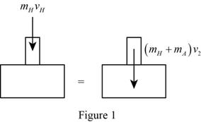
Use the principle of conservation of momentum to the impact of hammer head and anvil, to obtain the final velocity of anvil and hammer after the impact.
The expression for the principle of conservation of momentum as follows;
Initially the anvil is at rest, so the velocity will be zero.
Substitute 0 for
Show the free body impulse-momentum diagram of the hammer head as in Figure (2).
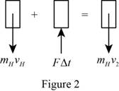
Use the principle of the impulse momentum to the hammer head to find the impulse exerted
The expression for the principle of the impulse momentum as follows;
Calculate the mass of the hammer
Substitute
The expression for the kinetic energy of the hammer before impact
Substitute
Calculate the final kinetic energy of the hammer and anvil system after the impact
Substitute
Substitute
Calculate the mass of the anvil
Here,
Substitute
Consider the equation (1).
Substitute
Consider the equation (2).
Substitute
Calculate the energy absorbed by the rivet
Consider the equation (3).
Substitute
Calculate the energy absorbed by the rivet under each blow
Substitute
Therefore, the impulsive force
(b)
Find the impulsive force
(b)
Answer to Problem 13.148P
The impulsive force
Explanation of Solution
Given information:
The weight of the hammer (W) is
The velocity of the hammer
The acceleration due to gravity (g) is
Calculation:
Calculate the impulse exerted by the rivet
Calculate the mass of the anvil
Substitute
Consider the equation (1).
Substitute
Consider the equation (2).
Substitute
Consider the equation (3).
Substitute
Calculate the energy absorbed by the rivet under each blow
Substitute
Want to see more full solutions like this?
Chapter 13 Solutions
VECTOR MECH...,STAT.+DYNA.(LL)-W/ACCESS


- The 120 kg wheel has a radius of gyration of 0.7 m. A force P with a magnitude of 50 N is applied at the edge of the wheel as seen in the diagram. The coefficient of static friction is 0.3, and the coefficient of kinetic friction is 0.25. Find the acceleration and angular acceleration of the wheel.arrow_forwardAuto Controls Using MATLAB , find the magnitude and phase plot of the compensators NO COPIED SOLUTIONSarrow_forward4-81 The corner shown in Figure P4-81 is initially uniform at 300°C and then suddenly exposed to a convection environment at 50°C with h 60 W/m². °C. Assume the = 2 solid has the properties of fireclay brick. Examine nodes 1, 2, 3, 4, and 5 and deter- mine the maximum time increment which may be used for a transient numerical calculation. Figure P4-81 1 2 3 4 1 cm 5 6 1 cm 2 cm h, T + 2 cmarrow_forward
- Auto Controls A union feedback control system has the following open loop transfer function where k>0 is a variable proportional gain i. for K = 1 , derive the exact magnitude and phase expressions of G(jw). ii) for K = 1 , identify the gaincross-over frequency (Wgc) [where IG(jo))| 1] and phase cross-overfrequency [where <G(jw) = - 180]. You can use MATLAB command "margin" to obtain there quantities. iii) Calculate gain margin (in dB) and phase margin (in degrees) ·State whether the closed-loop is stable for K = 1 and briefly justify your answer based on the margin . (Gain marginPhase margin) iv. what happens to the gain margin and Phase margin when you increase the value of K?you You can use for loop in MATLAB to check that.Helpful matlab commands : if, bode, margin, rlocus NO COPIED SOLUTIONSarrow_forwardAuto Controls Hand sketch the root Focus of the following transfer function How many asymptotes are there ?what are the angles of the asymptotes?Does the system remain stable for all values of K NO COPIED SOLUTIONSarrow_forward-400" 150" in Datum 80" 90" -280"arrow_forward
- 7) Please draw the front, top and side view for the following object. Please cross this line outarrow_forwardA 10-kg box is pulled along P,Na rough surface by a force P, as shown in thefigure. The pulling force linearly increaseswith time, while the particle is motionless att = 0s untilit reaches a maximum force of100 Nattimet = 4s. If the ground has staticand kinetic friction coefficients of u, = 0.6 andHU, = 0.4 respectively, determine the velocityof the A 1 0 - kg box is pulled along P , N a rough surface by a force P , as shown in the figure. The pulling force linearly increases with time, while the particle is motionless at t = 0 s untilit reaches a maximum force of 1 0 0 Nattimet = 4 s . If the ground has static and kinetic friction coefficients of u , = 0 . 6 and HU , = 0 . 4 respectively, determine the velocity of the particle att = 4 s .arrow_forwardCalculate the speed of the driven member with the following conditions: Diameter of the motor pulley: 4 in Diameter of the driven pulley: 12 in Speed of the motor pulley: 1800 rpmarrow_forward
 Elements Of ElectromagneticsMechanical EngineeringISBN:9780190698614Author:Sadiku, Matthew N. O.Publisher:Oxford University Press
 Mechanics of Materials (10th Edition)Mechanical EngineeringISBN:9780134319650Author:Russell C. HibbelerPublisher:PEARSON
 Thermodynamics: An Engineering ApproachMechanical EngineeringISBN:9781259822674Author:Yunus A. Cengel Dr., Michael A. BolesPublisher:McGraw-Hill Education
 Control Systems EngineeringMechanical EngineeringISBN:9781118170519Author:Norman S. NisePublisher:WILEY
 Mechanics of Materials (MindTap Course List)Mechanical EngineeringISBN:9781337093347Author:Barry J. Goodno, James M. GerePublisher:Cengage Learning
 Engineering Mechanics: StaticsMechanical EngineeringISBN:9781118807330Author:James L. Meriam, L. G. Kraige, J. N. BoltonPublisher:WILEY