
Concept explainers
Videos
(a)
Find the distance (x) required to bring the train to stop.
(a)
Answer to Problem 13.17P
The distance (x) required to bring the train to stop is
Explanation of Solution
Given information:
The initial speed of the train
The coefficient of kinetic friction
The weight of train A
The weight of train B
The weight of train C
Assume the acceleration due to gravity (g) is
Calculation:
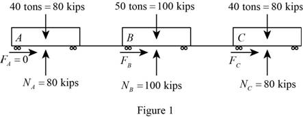
Show the free body diagram of the train A, B and C with the forces as in Figure (1).
Convert the unit of initial velocity of trailer truck from
Calculate the force at A
Substitute 0.35 for
Calculate the force at B
Substitute 0.35 for
Calculate the force at C
Substitute 0.35 for
Calculate the total weight (W) using the relation:
Substitute
Calculate the mass of the truck (m) using the formula:
Substitute
Calculate the initial kinetic energy
Substitute
The final kinetic energy
Calculate work done
Substitute
Use work and energy principle which states that kinetic energy of the particle at a displaced point can be obtained by adding the initial kinetic energy and the work done on the particle during its displacement.
Find the distance (x) required to bring the train to stop:
Substitute
Therefore, the distance (x) required to bring the train to stop is
(b)
Find the force in each coupling.
(b)
Answer to Problem 13.17P
The force in coupling AB is
The force in coupling BC is
Explanation of Solution
Given information:
The initial speed of the train
The coefficient of kinetic friction
The weight of train A
The weight of train B
The weight of train C
Assume the acceleration due to gravity (g) is
Calculation:
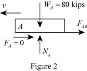
Consider car A:
Show the free body diagram of the train A with the forces as in Figure (2).
Assume
Calculate the mass of the truck (m) using the formula:
Substitute
Calculate the initial kinetic energy
Substitute
The final kinetic energy
Calculate work done
Substitute
Use work and energy principle which states that kinetic energy of the particle at a displaced point can be obtained by adding the initial kinetic energy and the work done on the particle during its displacement.
The expression for the principle of work and energy is as follows;
Substitute
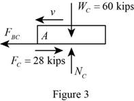
Consider car C:
Show the free body diagram of the train C with the forces as in Figure (3).
Calculate the mass of the truck (m) using the formula:
Substitute
Calculate the initial kinetic energy
Substitute
The final kinetic energy
Calculate work done
Substitute
Use work and energy principle which states that kinetic energy of the particle at a displaced point can be obtained by adding the initial kinetic energy and the work done on the particle during its displacement.
Find the force in coupling BC:
Substitute
Therefore, the forces in coupling AB and BC are
Want to see more full solutions like this?
Chapter 13 Solutions
<LCPO> VECTOR MECH,STAT+DYNAMICS


- 4. In the figure, shaft A made of AISI 1010 hot-rolled steel, is welded to a fixed support and is subjected to loading by equal and opposite Forces F via shaft B. Stress concentration factors K₁ (1.7) and Kts (1.6) are induced by the 3mm fillet. Notch sensitivities are q₁=0.9 and qts=1. The length of shaft A from the fixed support to the connection at shaft B is 1m. The load F cycles from 0.5 to 2kN and a static load P is 100N. For shaft A, find the factor of safety (for infinite life) using the modified Goodman fatigue failure criterion. 3 mm fillet Shaft A 20 mm 25 mm Shaft B 25 mmarrow_forwardPlease sovle this for me and please don't use aiarrow_forwardPlease sovle this for me and please don't use aiarrow_forward
- 3. The cold-drawn AISI 1040 steel bar shown in the figure is subjected to a completely reversed axial load fluctuating between 28 kN in compression to 28 kN in tension. Estimate the fatigue factor of safety based on achieving infinite life (using Goodman line) and the yielding factor of safety. If infinite life is not predicted, estimate the number of cycles to failure. 25 mm + 6-mm D. 10 mmarrow_forwardCORRECT AND DETAILED SOLUTION WITH FBD ONLY. I WILL UPVOTE 1. The truss shown is supported by hinge at A and cable at E.Given: H = 4m, S = 1.5 m, α = 75⁰, θ = 33⁰.Allowable tensile stress in cable = 64 MPa.Allowable compressive stress in all members = 120 MPaAllowable tensile stress in all members = 180 MPa1.Calculate the maximum permissible P, in kN, if the diameter of the cable is 20 mm.2.If P = 40 kN, calculate the required area (mm2) of member BC.3. If members have solid square section, with dimension 15 mm, calculate the maximum permissible P (kN) based on the allowable strength of member HI.ANSWERS: (1) 45.6 kN; (2) 83.71 mm2; (3) 171.76 kNarrow_forwardCORRECT AND DETAILED SOLUTION WITH FBD ONLY. I WILL UPVOTE 2: A wire 4 meters long is stretched horizontally between points 4 meters apart. The wire is 25 mm2 in cross-section with a modulus of elasticity of 200 GPa. A load W placed at the center of the wire produces a sag Δ.1.Calculate the tension (N) in the wire if sag Δ = 30 mm.2.Calculate the magnitude of W, in N, if sag Δ = 54.3 mm.3. If W is 60 N, what is the sag (in mm)?ANSWERS: (1) 562 N, (2) 100 N, (3) 45.8 Narrow_forward
- CORRECT AND DETAILED SOLUTION WITH FBD ONLY. I WILL UPVOTE 4 : A cable and pulley system at D is used to bring a 230-kg pole (ACB) to a vertical position as shown. The cable has tensile force T and is attached at C. The length of the pole is 6.0 m, the outer diameter is d = 140 mm, and the wall thickness t = 12 mm. The pole pivots about a pin at A. The allowable shear stress in the pin is 60 MPa and the allowable bearing stress is 90 MPa. The diameter of the cable is 8 mm.1.Find the minimum diameter (mm) of the pin at A to support the weight of the pole in the position shown.2.Calculate the elongation (mm) of the cable CD.3.Calculate the vertical displacement of point C, in mm.ANSWERS: (1) 6 mm, (2) 1.186 mm, (3) 1.337 mm--arrow_forward1. Derive an expression for H(w) filter or bandpass/reject filter. = for the circuit below. Qualitatively determine if it's a high/lowpass L ell R ww Voarrow_forward2. Obtain the transfer function, H(w) = 0 for the circuit below for R₁ = 1 kQ2, R2 = 10 kQ, and Vi C = 1 μF. What role, if any, does the capacitor play? Explain. R₁ R2 + C + Voarrow_forward
 Elements Of ElectromagneticsMechanical EngineeringISBN:9780190698614Author:Sadiku, Matthew N. O.Publisher:Oxford University Press
 Mechanics of Materials (10th Edition)Mechanical EngineeringISBN:9780134319650Author:Russell C. HibbelerPublisher:PEARSON
 Thermodynamics: An Engineering ApproachMechanical EngineeringISBN:9781259822674Author:Yunus A. Cengel Dr., Michael A. BolesPublisher:McGraw-Hill Education
 Control Systems EngineeringMechanical EngineeringISBN:9781118170519Author:Norman S. NisePublisher:WILEY
 Mechanics of Materials (MindTap Course List)Mechanical EngineeringISBN:9781337093347Author:Barry J. Goodno, James M. GerePublisher:Cengage Learning
 Engineering Mechanics: StaticsMechanical EngineeringISBN:9781118807330Author:James L. Meriam, L. G. Kraige, J. N. BoltonPublisher:WILEY