
Videos
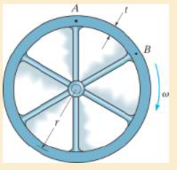
The rim on the flywheel has a thickness t, width b, and specific weight γ. If the flywheel is rotating at a constant rate of ω, determine the maximum moment developed in the rim. Assume that the spokes do not deform. Hint: Due to symmetry of the loading, the slope of the rim at each spoke is zero. Consider the radius to be sufficiently large so that the segment AB can be considered as a straight beam fixed at both ends and loaded with a uniform centrifugal force per unit length. Show that this force is w = btγω2r/g.
Want to see the full answer?
Check out a sample textbook solution
Chapter 12 Solutions
MECHANICS OF MATERIALS
Additional Engineering Textbook Solutions
Thermodynamics: An Engineering Approach
Modern Database Management
Vector Mechanics For Engineers
Electric Circuits. (11th Edition)
Problem Solving with C++ (10th Edition)
Starting Out with C++: Early Objects (9th Edition)


- PROBLEM 3.46 The solid cylindrical rod BC of length L = 600 mm is attached to the rigid lever AB of length a = 380 mm and to the support at C. When a 500 N force P is applied at A, design specifications require that the displacement of A not exceed 25 mm when a 500 N force P is applied at A For the material indicated determine the required diameter of the rod. Aluminium: Tall = 65 MPa, G = 27 GPa. Aarrow_forwardFind the equivalent mass of the rocker arm assembly with respect to the x coordinate. k₁ mi m2 k₁arrow_forward2. Figure below shows a U-tube manometer open at both ends and containing a column of liquid mercury of length l and specific weight y. Considering a small displacement x of the manometer meniscus from its equilibrium position (or datum), determine the equivalent spring constant associated with the restoring force. Datum Area, Aarrow_forward
- 1. The consequences of a head-on collision of two automobiles can be studied by considering the impact of the automobile on a barrier, as shown in figure below. Construct a mathematical model (i.e., draw the diagram) by considering the masses of the automobile body, engine, transmission, and suspension and the elasticity of the bumpers, radiator, sheet metal body, driveline, and engine mounts.arrow_forward3.) 15.40 – Collar B moves up at constant velocity vB = 1.5 m/s. Rod AB has length = 1.2 m. The incline is at angle = 25°. Compute an expression for the angular velocity of rod AB, ė and the velocity of end A of the rod (✓✓) as a function of v₂,1,0,0. Then compute numerical answers for ȧ & y_ with 0 = 50°.arrow_forward2.) 15.12 The assembly shown consists of the straight rod ABC which passes through and is welded to the grectangular plate DEFH. The assembly rotates about the axis AC with a constant angular velocity of 9 rad/s. Knowing that the motion when viewed from C is counterclockwise, determine the velocity and acceleration of corner F.arrow_forward
 International Edition---engineering Mechanics: St...Mechanical EngineeringISBN:9781305501607Author:Andrew Pytel And Jaan KiusalaasPublisher:CENGAGE L