
Mechanics of Materials
10th Edition
ISBN: 9780134321158
Author: HIBBELER
Publisher: PEARSON
expand_more
expand_more
format_list_bulleted
Concept explainers
Videos
Textbook Question
Chapter 12.5, Problem 12.91P
The W24 × 104 A-36 steel beam is used to support the uniform distributed load and a concentrated force which is applied at its end. If the force acts at an angle with the vertical as shown, determine the horizontal and vertical displacement at A.
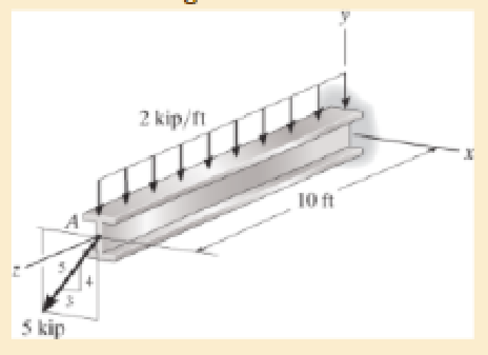
Prob. 12–91
Expert Solution & Answer
Want to see the full answer?
Check out a sample textbook solution
Students have asked these similar questions
The T-shaped structure is embedded in a concrete wall at A
and subjected to the force F₁ and the force-couple system
F2 1650 N and M = 1,800 N-m at the locations shown.
Neglect the weight of the structure in your calculations for
this problem.
=
a.) Compute the allowable range of magnitudes for F₁ in the
direction shown if the connection at A will fail when
subjected to a resultant moment with a magnitude of 920 N-
m or higher.
b.) Focusing on the forces and igonoring given M for now.
Using the value for F1, min that you calculated in (a), replace
the two forces F₁ and F2 with a single force that has
equivalent effect on the structure. Specify the equivalent
→>
force Feq in Cartesian components and indicate the
horizontal distance from point A to its line of action (note
this line of action may not intersect the structure).
c.) Now, model the entire force system (F1,min, F2, and M)
as a single force and couple acting at the junction of the
horizontal and vertical sections of the…
The heated rod from Problem 3 is subject to a volumetric heating
h(x) = h0
x
L in units of [Wm−3], as shown in the figure below. Under the
heat supply the temperature of the rod changes along x with the
temperature function T (x). The temperature T (x) is governed by the
d
following equations:
−
dx (q(x)) + h(x) = 0 PDE
q(x) =−k dT
dx Fourier’s law of heat conduction (4)
where q(x) is the heat flux through the rod and k is the (constant)
thermal conductivity. Both ends of the bar are in contact with a heat
reservoir at zero temperature.
Determine:
1. Appropriate BCs for this physical problem.
2. The temperature function T (x).
3. The heat flux function q(x).
Side Note: Please see that both ends of bar are in contact with a heat reservoir at zero temperature so the boundary condition at the right cannot be du/dx=0 because its not thermally insulated. Thank you
The elastic bar from Problem 1 spins with angular velocity ω about an axis, as shown in the figure below. The radial acceleration at a generic point x along the bar is a(x) = ω2x. Under this radial acceleration, the bar stretches along x with displacement function u(x). The displacement d u(x) is governed by the following equations: dx (σ(x)) + ρa(x) = 0 PDE σ(x) = E du dx Hooke’s law (2) where σ(x) is the axial stress in the rod, ρ is the mass density, and E is the (constant) Young’s modulus. The bar is pinned on the rotation axis at x = 0 and it is also pinned at x = L. Determine: 1. Appropriate BCs for this physical problem. 2. The displacement function u(x). 3. The stress function σ(x). SIDE QUESTION: I saw a tutor solve it before but I didn't understand why the tutor did not divide E under the second term (c1x) before finding u(x). The tutor only divided E under first term. please explain and thank you
Chapter 12 Solutions
Mechanics of Materials
Ch. 12.2 - In each case, determine the internal bending...Ch. 12.2 - Determine the slope and deflection of end A of the...Ch. 12.2 - Determine the slope and deflection of end A of the...Ch. 12.2 - Determine the slope of end A of the cantilevered...Ch. 12.2 - Determine the maximum deflection of the simply...Ch. 12.2 - Determine the maximum deflection of the simply...Ch. 12.2 - Determine the slope of the simply supported beam...Ch. 12.2 - An L2 steel strap having a thickness of 0.125 in....Ch. 12.2 - The L2 steel blade of the band saw wraps around...Ch. 12.2 - A picture is taken of a man performing a pole...
Ch. 12.2 - El is constant. Prob. 124Ch. 12.2 - Determine the deflection of end C of the...Ch. 12.2 - Determine the elastic curve for the cantilevered...Ch. 12.2 - The A-36 steel beam has a depth of 10 in. and is...Ch. 12.2 - Determine the equations of the elastic curve using...Ch. 12.2 - Determine the equations of the elastic curve for...Ch. 12.2 - Determine the equations of the elastic curve using...Ch. 12.2 - Determine the equations of the elastic curve using...Ch. 12.2 - Draw the bending-moment diagram for the shaft and...Ch. 12.2 - Determine the maximum deflection of the beam and...Ch. 12.2 - The simply supported shaft has a moment of inertia...Ch. 12.2 - A torque wrench is used to tighten the nut on a...Ch. 12.2 - The pipe can be assumed roller supported at its...Ch. 12.2 - Determine the equations of the elastic curve for...Ch. 12.2 - The bar is supported by a roller constraint at B,...Ch. 12.2 - Determine the deflection at B of the bar in Prob....Ch. 12.2 - Determine the equations of the elastic curve using...Ch. 12.2 - Determine the maximum deflection of the solid...Ch. 12.2 - Determine the elastic curve for the cantilevered...Ch. 12.2 - Determine the equations of the elastic curve using...Ch. 12.2 - Determine the equations of the elastic curve using...Ch. 12.2 - The floor beam of the airplane is subjected to the...Ch. 12.2 - Determine the maximum deflection of the simply...Ch. 12.2 - The beam is made of a material having a specific...Ch. 12.2 - Determine the slope at end B and the maximum...Ch. 12.2 - Determine the equation of the elastic curve using...Ch. 12.2 - Determine the equations of the elastic curve using...Ch. 12.3 - The shaft is supported at A by a journal bearing...Ch. 12.3 - The shaft supports the two pulley loads shown....Ch. 12.3 - The beam is made of a ceramic material. If it is...Ch. 12.3 - Determine the equation of the elastic curve, the...Ch. 12.3 - The beam is subjected to the load shown. Determine...Ch. 12.3 - Determine the equation of the elastic curve, the...Ch. 12.3 - Determine the equation of the elastic curve and...Ch. 12.3 - The shaft supports the two pulley loads. Determine...Ch. 12.3 - Determine the maximum deflection of the...Ch. 12.3 - Determine the slope at A and the deflection of end...Ch. 12.3 - Determine the maximum deflection in region AB of...Ch. 12.3 - Prob. 12.42PCh. 12.3 - Prob. 12.43PCh. 12.3 - Prob. 12.44PCh. 12.3 - Prob. 12.45PCh. 12.3 - Prob. 12.46PCh. 12.3 - Prob. 12.47PCh. 12.3 - Determine the value of a so that the displacement...Ch. 12.3 - Determine the displacement at C and the slope at...Ch. 12.3 - Determine the equations of the slope and elastic...Ch. 12.4 - Determine the slope and deflection of end A of the...Ch. 12.4 - Determine the slope and deflection of end A of the...Ch. 12.4 - Determine the slope and deflection of end A of the...Ch. 12.4 - Determine the slope and deflection at A of the...Ch. 12.4 - Prob. 12.11FPCh. 12.4 - Determine the maximum deflection of the simply...Ch. 12.4 - Determine the slope and deflection at C. El is...Ch. 12.4 - Determine the slope and deflection at C. El is...Ch. 12.4 - Determine the deflection of end B of the...Ch. 12.4 - Prob. 12.54PCh. 12.4 - The composite simply supported steel shaft is...Ch. 12.4 - Prob. 12.56PCh. 12.4 - Prob. 12.57PCh. 12.4 - Determine the deflection at C and the slope of the...Ch. 12.4 - Determine the maximum deflection of the...Ch. 12.4 - Prob. 12.60PCh. 12.4 - Determine the position a of the roller support B...Ch. 12.4 - Prob. 12.62PCh. 12.4 - Determine the slope and the deflection of end B of...Ch. 12.4 - The two A-36 steel bars have a thickness of 1 in....Ch. 12.4 - Determine the slope at A and the displacement at...Ch. 12.4 - Determine the deflection at C and the slopes at...Ch. 12.4 - Determine the maximum deflection within region AB....Ch. 12.4 - Determine the slope at A and the maximum...Ch. 12.4 - Determine the slope at C and the deflection at B....Ch. 12.4 - Determine the slope at A and the maximum...Ch. 12.4 - Determine the displacement of the 20-mm-diameter...Ch. 12.4 - The two force components act on the tire of the...Ch. 12.4 - Prob. 12.73PCh. 12.4 - The rod is constructed from two shafts for which...Ch. 12.4 - Prob. 12.75PCh. 12.4 - Determine the slope at point A and the maximum...Ch. 12.4 - Determine the position a of roller support B in...Ch. 12.4 - Determine the slope at B and deflection at C. El...Ch. 12.4 - Prob. 12.79PCh. 12.4 - Prob. 12.80PCh. 12.4 - Prob. 12.81PCh. 12.4 - Determine the maximum deflection of the beam. El...Ch. 12.5 - The W10 15 cantilevered beam is made of A-36...Ch. 12.5 - The W10 15 cantilevered beam is made of A-36...Ch. 12.5 - The W14 43 simply supported beam is made of A992...Ch. 12.5 - The W14 43 simply supported beam is made of A992...Ch. 12.5 - The W14 43 simply supported beam is made of A-36...Ch. 12.5 - The W14 43 simply supported beam is made of A-36...Ch. 12.5 - The W8 48 cantilevered beam is made of A-36 steel...Ch. 12.5 - The beam supports the loading shown. Code...Ch. 12.5 - The W24 104 A-36 steel beam is used to support...Ch. 12.5 - The W8 48 cantilevered beam is made of A-36 steel...Ch. 12.5 - The rod is pinned at its end A and attached to a...Ch. 12.5 - Prob. 12.94PCh. 12.5 - The pipe assembly consists of three equal-sized...Ch. 12.5 - The assembly consists of a cantilevered beam CS...Ch. 12.5 - Determine the smallest force F required to attract...Ch. 12.5 - Prob. 12.98PCh. 12.7 - Determine the reactions at the supports A and B,...Ch. 12.7 - Determine the reactions at the supports, then draw...Ch. 12.7 - Determine the reactions at the supports A, B, and...Ch. 12.7 - Determine the reactions at the supports A and B,...Ch. 12.7 - Determine the reactions at the supports A and B,...Ch. 12.7 - Determine the moment reactions at the supports A...Ch. 12.7 - Determine the reactions at the supports A and B,...Ch. 12.7 - Determine the reactions at the support A and B. EI...Ch. 12.7 - Determine the reactions at roller support A and...Ch. 12.7 - Determine the moment reactions at the supports A...Ch. 12.7 - The beam has a constant E1I1 and is supported by...Ch. 12.7 - The beam is supported by a pin at A, a roller at...Ch. 12.8 - Determine the moment reactions at the supports A...Ch. 12.8 - Determine the reaction at the supports, then draw...Ch. 12.8 - Determine the vertical reaction at the journal...Ch. 12.8 - Determine the reactions at the supports A and B,...Ch. 12.8 - Determine the reactions at the supports. EI is...Ch. 12.8 - Determine the vertical reaction at the journal...Ch. 12.9 - Determine the reactions at the fixed support A and...Ch. 12.9 - Determine the reactions at the fixed support A and...Ch. 12.9 - Determine the reactions at the fixed support A and...Ch. 12.9 - Determine the reaction at the roller B. EI is...Ch. 12.9 - Determine the reaction at the roller B. EI is...Ch. 12.9 - Determine the reaction at the roller support B if...Ch. 12.9 - Determine the reactions at the journal bearing...Ch. 12.9 - Determine the reactions at the supports, then draw...Ch. 12.9 - Determine the reactions at the supports, then draw...Ch. 12.9 - Determine the reactions at the supports A and B....Ch. 12.9 - The beam is used to support the 20-kip load....Ch. 12.9 - Determine the reactions at the supports A and B....Ch. 12.9 - Determine the reactions at the supports A and B....Ch. 12.9 - Before the uniform distributed load is applied to...Ch. 12.9 - The fixed supported beam AB is strengthened using...Ch. 12.9 - The beam has a constant E1I1, and is supported by...Ch. 12.9 - The beam is supported by the bolted supports at...Ch. 12.9 - Each of the two members is made from 6061-T6...Ch. 12.9 - The beam is made from a soft linear elastic...Ch. 12.9 - The beam AB has a moment of inertia I = 475 in4...Ch. 12.9 - The rim on the flywheel has a thickness t, width...Ch. 12.9 - Determine the moment developed in each corner....Ch. 12 - Determine the equation of the elastic curve. Use...Ch. 12 - Draw the bending-moment diagram for the shaft and...Ch. 12 - Determine the moment reactions at the supports A...Ch. 12 - Specify the slope at A and the maximum deflection....Ch. 12 - Determine the maximum deflection between the...Ch. 12 - Determine the slope at B and the deflection at C....Ch. 12 - Determine the reactions, then draw the shear and...Ch. 12 - El is constant.Ch. 12 - Using the method of superposition, determine the...
Knowledge Booster


Learn more about
Need a deep-dive on the concept behind this application? Look no further. Learn more about this topic, mechanical-engineering and related others by exploring similar questions and additional content below.Similar questions
- calculate the total power required to go 80 mph in a VW Type 2 Samba Bus weighing 2310 lbs. with a Cd of 0.35 and a frontal area of 30ft^2. Consider the coefficient of rolling resistance to be 0.018. What is the increase in power required to go the same speed if the weight is increased by 2205 pounds (the rated carrying capacity of the vehicle). If the rated power for the vehicle is 49 bhp, will the van be able to reach 80 mph at full carrying capacity?arrow_forwardA distillation column with a total of 13 actual stages (including a partial condenser) is used to perform a separation which requires 7 ideal stages. Calculate the overall column efficiency, and report your answer in %arrow_forward6. Consider a 10N step input to the mechanical system shown below, take M = 15kg, K = 135N/m, and b = 0.4 Ns/m. (a) Assume zero initial condition, calculate the (i) System pole (ii) System characterization, and (iii) The time domain response (b) Calculate the steady-state value of the system b [ www K 个 х M -F(+)arrow_forward
- 2. Solve the following linear time invariant differential equations using Laplace transforms subject to different initial conditions (a) y-y=t for y(0) = 1 and y(0) = 1 (b) ÿ+4y+ 4y = u(t) for y(0) = 0 and y(0) = 1 (c) y-y-2y=0 for y(0) = 1 and y(0) = 0arrow_forward3. For the mechanical systems shown below, the springs are undeflected when x₁ = x2 = x3 = 0 and the input is given as fa(t). Draw the free-body diagrams and write the modeling equations governing each of the systems. K₁ 000 K₂ 000 M₁ M2 -fa(t) B₂ B₁ (a) fa(t) M2 K₂ 000 B K₁ x1 000 M₁ (b)arrow_forwardThis question i m uploading second time . before you provide me incorrect answer. read the question carefully and solve accordily.arrow_forward
- 1. Create a table comparing five different analogous variables for translational, rotational, electrical and fluid systems. Include the standard symbols for each variable in their respective systems.arrow_forward2) Suppose that two unequal masses m₁ and m₂ are moving with initial velocities v₁ and v₂, respectively. The masses hit each other and have a coefficient of restitution e. After the impact, mass 1 and 2 head to their respective gaps at angles a and ẞ, respectively. Derive expressions for each of the angles in terms of the initial velocities and the coefficient of restitution. m1 m2 8 m1 m2 βarrow_forward4. Find the equivalent spring constant and equivalent viscous-friction coefficient for the systems shown below. @ B₁ B₂ H B3 (b)arrow_forward
- 5. The cart shown below is inclined 30 degrees with respect to the horizontal. At t=0s, the cart is released from rest (i.e. with no initial velocity). If the air resistance is proportional to the velocity squared. Analytically determine the initial acceleration and final or steady-state velocity of the cart. Take M= 900 kg and b 44.145 Ns²/m². Mg -bx 2 отarrow_forward9₁ A Insulated boundary Insulated boundary dx Let's begin with the strong form for a steady-state one-dimensional heat conduction problem, without convection. d dT + Q = dx dx According to Fourier's law of heat conduction, the heat flux q(x), is dT q(x)=-k dx. x Q is the internal heat source, which heat is generated per unit time per unit volume. q(x) and q(x + dx) are the heat flux conducted into the control volume at x and x + dx, respectively. k is thermal conductivity along the x direction, A is the cross-section area perpendicular to heat flux q(x). T is the temperature, and is the temperature gradient. dT dx 1. Derive the weak form using w(x) as the weight function. 2. Consider the following scenario: a 1D block is 3 m long (L = 3 m), with constant cross-section area A = 1 m². The left free surface of the block (x = 0) is maintained at a constant temperature of 200 °C, and the right surface (x = L = 3m) is insulated. Recall that Neumann boundary conditions are naturally satisfied…arrow_forward1 - Clearly identify the system and its mass and energy exchanges between each system and its surroundings by drawing a box to represent the system boundary, and showing the exchanges by input and output arrows. You may want to search and check the systems on the Internet in case you are not familiar with their operations. A pot with boiling water on a gas stove A domestic electric water heater A motor cycle driven on the roadfrom thermodynamics You just need to draw and put arrows on the first part a b and carrow_forward
arrow_back_ios
SEE MORE QUESTIONS
arrow_forward_ios
Recommended textbooks for you
 Elements Of ElectromagneticsMechanical EngineeringISBN:9780190698614Author:Sadiku, Matthew N. O.Publisher:Oxford University Press
 Mechanics of Materials (10th Edition)Mechanical EngineeringISBN:9780134319650Author:Russell C. HibbelerPublisher:PEARSON
 Thermodynamics: An Engineering ApproachMechanical EngineeringISBN:9781259822674Author:Yunus A. Cengel Dr., Michael A. BolesPublisher:McGraw-Hill Education
 Control Systems EngineeringMechanical EngineeringISBN:9781118170519Author:Norman S. NisePublisher:WILEY
 Mechanics of Materials (MindTap Course List)Mechanical EngineeringISBN:9781337093347Author:Barry J. Goodno, James M. GerePublisher:Cengage Learning
 Engineering Mechanics: StaticsMechanical EngineeringISBN:9781118807330Author:James L. Meriam, L. G. Kraige, J. N. BoltonPublisher:WILEY
Elements Of Electromagnetics
Mechanical Engineering
ISBN:9780190698614
Author:Sadiku, Matthew N. O.
Publisher:Oxford University Press
Mechanics of Materials (10th Edition)
Mechanical Engineering
ISBN:9780134319650
Author:Russell C. Hibbeler
Publisher:PEARSON
Thermodynamics: An Engineering Approach
Mechanical Engineering
ISBN:9781259822674
Author:Yunus A. Cengel Dr., Michael A. Boles
Publisher:McGraw-Hill Education
Control Systems Engineering
Mechanical Engineering
ISBN:9781118170519
Author:Norman S. Nise
Publisher:WILEY
Mechanics of Materials (MindTap Course List)
Mechanical Engineering
ISBN:9781337093347
Author:Barry J. Goodno, James M. Gere
Publisher:Cengage Learning
Engineering Mechanics: Statics
Mechanical Engineering
ISBN:9781118807330
Author:James L. Meriam, L. G. Kraige, J. N. Bolton
Publisher:WILEY
Types Of loads - Engineering Mechanics | Abhishek Explained; Author: Prime Course;https://www.youtube.com/watch?v=4JVoL9wb5yM;License: Standard YouTube License, CC-BY