
Mechanics of Materials (10th Edition)
10th Edition
ISBN: 9780134319650
Author: Russell C. Hibbeler
Publisher: PEARSON
expand_more
expand_more
format_list_bulleted
Concept explainers
Videos
Textbook Question
Chapter 12.4, Problem 12.7FP
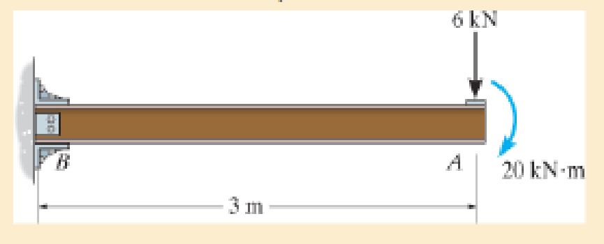
Determine the slope and deflection of end A of the cantilevered beam. E = 200 GPa and I = 65.0(10−6) m4.
F12–7
Expert Solution & Answer

Learn your wayIncludes step-by-step video

schedule06:17
Students have asked these similar questions
The figure illustrates the nonpermanent connection of a steel cylinder head to a grade 30 cast-iron pressure vessel using
73 bolts. A confined gasket seal has an effective sealing diameter D of 0.9 m. The cylinder pressure is cycled between a
minimum pressure of zero and a maximum pressure p, of 535 kPa. For the specifications given in the table for the
specific problem assigned, select a suitable bolt length from the preferred sizes. Use Table A-17 for calculation purposes.
Parameter
Head thickness, A
Cylinder thickness, B
Value
16 mm
25 mm
Internal diameter of the cylinder, C
0.8 m
Gasket sealing diameter, D
Bolt circle diameter, E
Outer diameter of the cylinder head, F
0.9 m
1.0 m
1.1 m
Bolt grade
ISO 10.9
Bolt diameter, d
10 mm
F
E
D
111
Find a suitable bolt length. Then, determine the bolt stiffness, material stiffness and stiffness constant of the joint.
The bolt length is
The bolt stiffness is
mm.
MN/m.
The material stiffness is |
The stiffness constant is
MN/m.
Problem 3
A rotating shaft of 20 mm diameter is simply supported.
The shaft is loaded with a transverse load of 10 kN as shown in
the figure. The shaft is made from AISI 1095 hot-rolled steel. The
surface has been machined. The shaft operate at
temperature T = 450 °C. Consider a reliability factor of 95%.
Determine
(a) Calculate the reaction forces R₁ and R2*
(b) Draw the shear force and bending moment diagrams
and determine the maximum bending moment and
shear force.
200 mm
20 mm
10,000 N
-50 mm-
C
A
B
R₁
Not to scale.
(c) Determine the critical location of the shaft and the maximum effective stresses,
(d) Calculate the static safety factor against yielding.
(e) Determined the endurance limit, adjusted as necessary with Marin factors.
(f)
Calculate the fatigue factor of safety based on achieving infinite life
(g)
If the fatigue factor of safety is less than 1, then estimate the life of the part in number of rotations, based on the ultimate
strength of the material at T = 450 °C.
An air duct heater consists of an aligned array of electrical heating elements in which the longitudinal and transverse pitches are SL = ST = 24 mm. There are 3 rows of elements in the flow direction (NL = 3) and 4 elements per row (NT = 4). Atmospheric air with an upstream velocity of 12 m/s and a temperature of 25°C moves in cross flow over the elements, which have a diameter of 12 mm, a length of 250 mm, and are maintained at a surface temperature of 350°C.
(a) Determine the total rate of heat transfer to the air and the temperature of the air leaving the duct heater.
(b) Determine the pressure drop across the element bank and the fan power requirement.
(c) Compare the average convection coefficient obtained in your analysis with the value for an isolated (single) element. Explain the difference between the results.
(d) What effect would increasing the longitudinal and transverse pitches to 30 mm have on the exit temperature of the air, the total heat rate, and the…
Chapter 12 Solutions
Mechanics of Materials (10th Edition)
Ch. 12.2 - In each case, determine the internal bending...Ch. 12.2 - Determine the slope and deflection of end A of the...Ch. 12.2 - Determine the slope and deflection of end A of the...Ch. 12.2 - Determine the slope of end A of the cantilevered...Ch. 12.2 - Determine the maximum deflection of the simply...Ch. 12.2 - Determine the maximum deflection of the simply...Ch. 12.2 - Determine the slope of the simply supported beam...Ch. 12.2 - An L2 steel strap having a thickness of 0.125 in....Ch. 12.2 - The L2 steel blade of the band saw wraps around...Ch. 12.2 - A picture is taken of a man performing a pole...
Ch. 12.2 - El is constant. Prob. 124Ch. 12.2 - Determine the deflection of end C of the...Ch. 12.2 - Determine the elastic curve for the cantilevered...Ch. 12.2 - The A-36 steel beam has a depth of 10 in. and is...Ch. 12.2 - Determine the equations of the elastic curve using...Ch. 12.2 - Determine the equations of the elastic curve for...Ch. 12.2 - Determine the equations of the elastic curve using...Ch. 12.2 - Determine the equations of the elastic curve using...Ch. 12.2 - Draw the bending-moment diagram for the shaft and...Ch. 12.2 - Determine the maximum deflection of the beam and...Ch. 12.2 - The simply supported shaft has a moment of inertia...Ch. 12.2 - A torque wrench is used to tighten the nut on a...Ch. 12.2 - The pipe can be assumed roller supported at its...Ch. 12.2 - Determine the equations of the elastic curve for...Ch. 12.2 - The bar is supported by a roller constraint at B,...Ch. 12.2 - Determine the deflection at B of the bar in Prob....Ch. 12.2 - Determine the equations of the elastic curve using...Ch. 12.2 - Determine the maximum deflection of the solid...Ch. 12.2 - Determine the elastic curve for the cantilevered...Ch. 12.2 - Determine the equations of the elastic curve using...Ch. 12.2 - Determine the equations of the elastic curve using...Ch. 12.2 - The floor beam of the airplane is subjected to the...Ch. 12.2 - Determine the maximum deflection of the simply...Ch. 12.2 - The beam is made of a material having a specific...Ch. 12.2 - Determine the slope at end B and the maximum...Ch. 12.2 - Determine the equation of the elastic curve using...Ch. 12.2 - Determine the equations of the elastic curve using...Ch. 12.3 - The shaft is supported at A by a journal bearing...Ch. 12.3 - The shaft supports the two pulley loads shown....Ch. 12.3 - The beam is made of a ceramic material. If it is...Ch. 12.3 - Determine the equation of the elastic curve, the...Ch. 12.3 - The beam is subjected to the load shown. Determine...Ch. 12.3 - Determine the equation of the elastic curve, the...Ch. 12.3 - Determine the equation of the elastic curve and...Ch. 12.3 - The shaft supports the two pulley loads. Determine...Ch. 12.3 - Determine the maximum deflection of the...Ch. 12.3 - Determine the slope at A and the deflection of end...Ch. 12.3 - Determine the maximum deflection in region AB of...Ch. 12.3 - Prob. 12.42PCh. 12.3 - Prob. 12.43PCh. 12.3 - Prob. 12.44PCh. 12.3 - Prob. 12.45PCh. 12.3 - Prob. 12.46PCh. 12.3 - Prob. 12.47PCh. 12.3 - Determine the value of a so that the displacement...Ch. 12.3 - Determine the displacement at C and the slope at...Ch. 12.3 - Determine the equations of the slope and elastic...Ch. 12.4 - Determine the slope and deflection of end A of the...Ch. 12.4 - Determine the slope and deflection of end A of the...Ch. 12.4 - Determine the slope and deflection of end A of the...Ch. 12.4 - Determine the slope and deflection at A of the...Ch. 12.4 - Prob. 12.11FPCh. 12.4 - Determine the maximum deflection of the simply...Ch. 12.4 - Determine the slope and deflection at C. El is...Ch. 12.4 - Determine the slope and deflection at C. El is...Ch. 12.4 - Determine the deflection of end B of the...Ch. 12.4 - Prob. 12.54PCh. 12.4 - The composite simply supported steel shaft is...Ch. 12.4 - Prob. 12.56PCh. 12.4 - Prob. 12.57PCh. 12.4 - Determine the deflection at C and the slope of the...Ch. 12.4 - Determine the maximum deflection of the...Ch. 12.4 - Prob. 12.60PCh. 12.4 - Determine the position a of the roller support B...Ch. 12.4 - Prob. 12.62PCh. 12.4 - Determine the slope and the deflection of end B of...Ch. 12.4 - The two A-36 steel bars have a thickness of 1 in....Ch. 12.4 - Determine the slope at A and the displacement at...Ch. 12.4 - Determine the deflection at C and the slopes at...Ch. 12.4 - Determine the maximum deflection within region AB....Ch. 12.4 - Determine the slope at A and the maximum...Ch. 12.4 - Determine the slope at C and the deflection at B....Ch. 12.4 - Determine the slope at A and the maximum...Ch. 12.4 - Determine the displacement of the 20-mm-diameter...Ch. 12.4 - The two force components act on the tire of the...Ch. 12.4 - Prob. 12.73PCh. 12.4 - The rod is constructed from two shafts for which...Ch. 12.4 - Prob. 12.75PCh. 12.4 - Determine the slope at point A and the maximum...Ch. 12.4 - Determine the position a of roller support B in...Ch. 12.4 - Determine the slope at B and deflection at C. El...Ch. 12.4 - Prob. 12.79PCh. 12.4 - Prob. 12.80PCh. 12.4 - Prob. 12.81PCh. 12.4 - Determine the maximum deflection of the beam. El...Ch. 12.5 - The W10 15 cantilevered beam is made of A-36...Ch. 12.5 - The W10 15 cantilevered beam is made of A-36...Ch. 12.5 - The W14 43 simply supported beam is made of A992...Ch. 12.5 - The W14 43 simply supported beam is made of A992...Ch. 12.5 - The W14 43 simply supported beam is made of A-36...Ch. 12.5 - The W14 43 simply supported beam is made of A-36...Ch. 12.5 - The W8 48 cantilevered beam is made of A-36 steel...Ch. 12.5 - The beam supports the loading shown. Code...Ch. 12.5 - The W24 104 A-36 steel beam is used to support...Ch. 12.5 - The W8 48 cantilevered beam is made of A-36 steel...Ch. 12.5 - The rod is pinned at its end A and attached to a...Ch. 12.5 - Prob. 12.94PCh. 12.5 - The pipe assembly consists of three equal-sized...Ch. 12.5 - The assembly consists of a cantilevered beam CS...Ch. 12.5 - Determine the smallest force F required to attract...Ch. 12.5 - Prob. 12.98PCh. 12.7 - Determine the reactions at the supports A and B,...Ch. 12.7 - Determine the reactions at the supports, then draw...Ch. 12.7 - Determine the reactions at the supports A, B, and...Ch. 12.7 - Determine the reactions at the supports A and B,...Ch. 12.7 - Determine the reactions at the supports A and B,...Ch. 12.7 - Determine the moment reactions at the supports A...Ch. 12.7 - Determine the reactions at the supports A and B,...Ch. 12.7 - Determine the reactions at the support A and B. EI...Ch. 12.7 - Determine the reactions at roller support A and...Ch. 12.7 - Determine the moment reactions at the supports A...Ch. 12.7 - The beam has a constant E1I1 and is supported by...Ch. 12.7 - The beam is supported by a pin at A, a roller at...Ch. 12.8 - Determine the moment reactions at the supports A...Ch. 12.8 - Determine the reaction at the supports, then draw...Ch. 12.8 - Determine the vertical reaction at the journal...Ch. 12.8 - Determine the reactions at the supports A and B,...Ch. 12.8 - Determine the reactions at the supports. EI is...Ch. 12.8 - Determine the vertical reaction at the journal...Ch. 12.9 - Determine the reactions at the fixed support A and...Ch. 12.9 - Determine the reactions at the fixed support A and...Ch. 12.9 - Determine the reactions at the fixed support A and...Ch. 12.9 - Determine the reaction at the roller B. EI is...Ch. 12.9 - Determine the reaction at the roller B. EI is...Ch. 12.9 - Determine the reaction at the roller support B if...Ch. 12.9 - Determine the reactions at the journal bearing...Ch. 12.9 - Determine the reactions at the supports, then draw...Ch. 12.9 - Determine the reactions at the supports, then draw...Ch. 12.9 - Determine the reactions at the supports A and B....Ch. 12.9 - The beam is used to support the 20-kip load....Ch. 12.9 - Determine the reactions at the supports A and B....Ch. 12.9 - Determine the reactions at the supports A and B....Ch. 12.9 - Before the uniform distributed load is applied to...Ch. 12.9 - The fixed supported beam AB is strengthened using...Ch. 12.9 - The beam has a constant E1I1, and is supported by...Ch. 12.9 - The beam is supported by the bolted supports at...Ch. 12.9 - Each of the two members is made from 6061-T6...Ch. 12.9 - The beam is made from a soft linear elastic...Ch. 12.9 - The beam AB has a moment of inertia I = 475 in4...Ch. 12.9 - The rim on the flywheel has a thickness t, width...Ch. 12.9 - Determine the moment developed in each corner....Ch. 12 - Determine the equation of the elastic curve. Use...Ch. 12 - Draw the bending-moment diagram for the shaft and...Ch. 12 - Determine the moment reactions at the supports A...Ch. 12 - Specify the slope at A and the maximum deflection....Ch. 12 - Determine the maximum deflection between the...Ch. 12 - Determine the slope at B and the deflection at C....Ch. 12 - Determine the reactions, then draw the shear and...Ch. 12 - El is constant.Ch. 12 - Using the method of superposition, determine the...
Additional Engineering Textbook Solutions
Find more solutions based on key concepts
Porter’s competitive forces model: The model is used to provide a general view about the firms, the competitors...
Management Information Systems: Managing The Digital Firm (16th Edition)
First to One Game This game is meant for two or more players. In the game, each player starts out with 50 point...
Starting Out with Java: From Control Structures through Data Structures (4th Edition) (What's New in Computer Science)
The job of the _____ is to fetch instructions, carry out the operations commanded by the instructions, and prod...
Starting Out With Visual Basic (8th Edition)
Fill in the blanks in each of the following statements: A relation that has no partial functional dependencies ...
Modern Database Management
1 void product() { 2int, a = 6; 3int b = 5; 4int c = 4; 5int result = a b c; 6System.out.printf("Result is %d...
Java How to Program, Early Objects (11th Edition) (Deitel: How to Program)
For the circuit shown, use the node-voltage method to find v1, v2, and i1.
How much power is delivered to the c...
Electric Circuits. (11th Edition)
Knowledge Booster


Learn more about
Need a deep-dive on the concept behind this application? Look no further. Learn more about this topic, mechanical-engineering and related others by exploring similar questions and additional content below.Similar questions
- What is the elongation of the rod in inches? And what is the change in diameter? I dont want either answer rounded please! Thank you.arrow_forwardDraw the shear and bending-moment diagrams for the beam and loading shown, and determine the maximum absolute value of (a) the shear, (b) the bending moment. 300 lb 240 lb 360 lb C D E A 4 in. 3 in. 4 in. 5 in. Fig. P12.5arrow_forwardA commercial office building is located in the city of Lansing, Michigan, and is heatedusing a gaseous fuel with a heating value of 725 Btu/std ft3. The indoor designtemperature is 71ºF. The heat load for the building is known to be 250,000 Btu/hr. Thisheat load accounts for the fact that there are internal heat gains in the building, due tothe presence of people and electronic equipment (e.g., lights and radios). People in thebuilding are usually seated and involved in light activity.a) The furnace had an initial efficiency factor of 73% when installed, but since thenefficiency-improvement retrofits were implemented that raised the efficiency factorto its present value of 82%. The building was designed using the 99% designheating temperature value for the city to determine the outdoor design temperature.Evaluate the annual fuel quantity (in std ft3) required to heat the building, using thedegree-day or bin method.b) Seventy people use the building, but the occupancy pattern for the…arrow_forward
- The volumetric flow rate of air through a duct transition of the type shown in Table 12-9b (rectangular with two parallel sides) is 2 m3/s. The duct before the transition issquare, with a height of 50 cm. The expansion ratio across the transition is 4 (i.e., theduct area after the transition is 4 times greater than the duct area before the transition).a) Determine the pressure loss (in Pa) across the transition if the exit from the duct isabrupt (i.e., the diverging angle of the transition is 180º).b) Determine the percentage reduction in pressure loss for a transition diverging angleof 20º compared to the one in part (a).c) The head HVAC engineer requires the pressure loss across the transition to bereduced to less than 50% of the pressure loss for an abrupt exit (i.e., the case in part(a)), and suggests a transition diverging angle of 45º. Will this new diverging angleachieve the required reduction in pressure loss? Justify your answer.d) For a transition diverging angle of 90º, the…arrow_forwardThe volumetric flow rate of air through a duct transition of the type shown in Table 12-9b (rectangular with two parallel sides) is 2 m3/s. The duct before the transition issquare, with a height of 50 cm. The expansion ratio across the transition is 4 (i.e., theduct area after the transition is 4 times greater than the duct area before the transition).a) Determine the pressure loss (in Pa) across the transition if the exit from the duct isabrupt (i.e., the diverging angle of the transition is 180º).b) Determine the percentage reduction in pressure loss for a transition diverging angleof 20º compared to the one in part (a).c) The head HVAC engineer requires the pressure loss across the transition to bereduced to less than 50% of the pressure loss for an abrupt exit (i.e., the case in part(a)), and suggests a transition diverging angle of 45º. Will this new diverging angleachieve the required reduction in pressure loss? Justify your answer.d) For a transition diverging angle of 90º, the…arrow_forwardAuto Controls The figure is a schematic diagram of an aircraft elevator control system. The input to the systemin the deflection angle of the control lever , and the output is the elevator angle phi.show that for each angle theta of the control lever ,there is a corresponding elevator angle phi. Then find Y(s)/theta(s) and simplify the resulting transfer function . Also note from the diagram that y and phi is related Show full solution, no copied solutionsarrow_forward
- hand-written solutions only. correct answers upvotedarrow_forwardFor a small house located in Ottawa, Ontario, there are three windows and three doors.You are assigned the task of determining the infiltration and related heat loss rates.It has been found experimentally that the pressure difference due to pressurization is -0.002 in. water. The pressure difference due to stack effect for this building is assumednegligible due to it having only a single floor. The dominant mean wind speed fordesign is assumed to be 15 mph. The house orientation is such that it is normal to thedominant mean wind direction.The house was built recently and all of the windows and doors are tight fitting. Thehouse construction and materials are typical for Ottawa, Ontario. The doors are 3 ftwide and 6.75 ft high. Each of the windows is double hung and each window has thefollowing overall dimensions: 3 ft wide and 4 ft high. (For clarity it is noted that eachdouble hung window has two glass segments that are 3 ft wide and 2 ft high.)The indoor design temperature is 70ºF and…arrow_forwardH.W1: Due to the applied loading, the element at point A on the solid cylinder is subjected to the state of stress shown. Determine the principal 6 ksi stresses acting at this point. 12 ksiarrow_forward
- A wall is 7 m wide and 3 m high, and contains two doors and one window. Details onthe wall components are as follows:• The window is a triple-glazed glass window with a 6.4 mm space filled withargon gas. The window surfaces do not have any special surface emissivitycoatings. The window dimensions are 2 m by 1 m, and the window has analuminum sash with a thermal break.• The wall material has an overall heat-transfer coefficient of 0.5 W/(m2-ºC).• Each door is a solid core flush door made of wood, with a thickness of 4.5 cm.Also, each door is 2.1 m high and 0.8 m wide. Both doors are accompanied bymetal storm doors.a) Determine the overall heat-transfer coefficient [in W/(m2-ºC)] for the wallcombination (based on the overall dimensions of the wall-window-doorscombination), assuming winter conditions.b) The room is maintained at a temperature of 22ºC. If the heat flow rate through thewall is 0.4 kW at a certain time, what is the outdoor temperature at that time?Infiltration can be…arrow_forwardhand-written solutions only. correct answers upvotearrow_forwardCan you use MATLAB?arrow_forward
arrow_back_ios
SEE MORE QUESTIONS
arrow_forward_ios
Recommended textbooks for you
 Elements Of ElectromagneticsMechanical EngineeringISBN:9780190698614Author:Sadiku, Matthew N. O.Publisher:Oxford University Press
 Mechanics of Materials (10th Edition)Mechanical EngineeringISBN:9780134319650Author:Russell C. HibbelerPublisher:PEARSON
 Thermodynamics: An Engineering ApproachMechanical EngineeringISBN:9781259822674Author:Yunus A. Cengel Dr., Michael A. BolesPublisher:McGraw-Hill Education
 Control Systems EngineeringMechanical EngineeringISBN:9781118170519Author:Norman S. NisePublisher:WILEY
 Mechanics of Materials (MindTap Course List)Mechanical EngineeringISBN:9781337093347Author:Barry J. Goodno, James M. GerePublisher:Cengage Learning
 Engineering Mechanics: StaticsMechanical EngineeringISBN:9781118807330Author:James L. Meriam, L. G. Kraige, J. N. BoltonPublisher:WILEY
Elements Of Electromagnetics
Mechanical Engineering
ISBN:9780190698614
Author:Sadiku, Matthew N. O.
Publisher:Oxford University Press
Mechanics of Materials (10th Edition)
Mechanical Engineering
ISBN:9780134319650
Author:Russell C. Hibbeler
Publisher:PEARSON
Thermodynamics: An Engineering Approach
Mechanical Engineering
ISBN:9781259822674
Author:Yunus A. Cengel Dr., Michael A. Boles
Publisher:McGraw-Hill Education
Control Systems Engineering
Mechanical Engineering
ISBN:9781118170519
Author:Norman S. Nise
Publisher:WILEY
Mechanics of Materials (MindTap Course List)
Mechanical Engineering
ISBN:9781337093347
Author:Barry J. Goodno, James M. Gere
Publisher:Cengage Learning
Engineering Mechanics: Statics
Mechanical Engineering
ISBN:9781118807330
Author:James L. Meriam, L. G. Kraige, J. N. Bolton
Publisher:WILEY
Solids: Lesson 53 - Slope and Deflection of Beams Intro; Author: Jeff Hanson;https://www.youtube.com/watch?v=I7lTq68JRmY;License: Standard YouTube License, CC-BY