Concept explainers
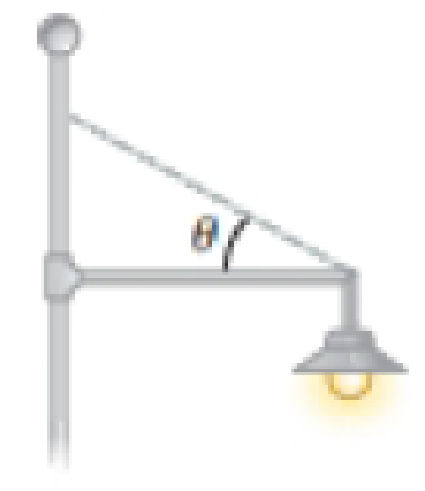
A 20.0-kg floodlight in a park is supported at the end of a horizontal beam of negligible mass that is hinged to a pole as shown in Figure P12.10. A cable at an angle of θ = 30.0° with the beam helps support the light. (a) Draw a force diagram for the beam. By computing torques about an axis at the hinge at the left-hand end of the beam, find (b) the tension in the cable, (c) the horizontal component of the force exerted by the pole on the beam, and (d) the vertical component of this force. Now solve the same problem from the force diagram from part (a) by computing torques around the junction between the cable and the beam at the right-hand end of the beam. Find (e) the vertical component of the force exerted by the pole on the beam, (f) the tension in the cable, and (g) the horizontal component of the force exerted by the pole on the beam. (h) Compare the solution to parts (b) through (d) with the solution to parts (c) through (g). Is either solution more accurate?
Figure P12.10

(a)
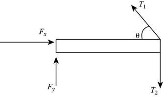
To draw: A force diagram for the beam.
Answer to Problem 18P
A force diagram for the beam is,

Explanation of Solution
Force diagram contains all the forces acting on the body. It contains the direction of each force acting on the body represent by vectors.
The hinged support have two reactions, one is vertical reaction and another is horizontal reaction. The tension force is acting at an angle
A force diagram for the beam is,

(b)
The tension in the cable.
Answer to Problem 18P
The tension in the cable is
Explanation of Solution
Given Information: The mass of a floodlight supported at the end of a horizontal beam is
Write the expression for the weight of the floodlight is acting downward.
Here,
Write the expression for the moment at the hinged point is,
Calculate moment at hinge point.
Here,
Substitute
Substitute
Conclusion:
Therefore, the tension in the cable is
(c)
The horizontal component of the force exerted by the pole on the beam.
Answer to Problem 18P
The horizontal component of the force exerted by the pole on the beam is
Explanation of Solution
Given Information: The tension in the cable is
Write the expression for the horizontal component of the force exerted by the pole on the beam.
Here,
Substitute
Conclusion:
Therefore, the horizontal component of the force exerted by the pole on the beam is
(d)
The vertical component of the force exerted by the pole on the beam.
Answer to Problem 18P
The vertical component of the force exerted by the pole on the beam is
Explanation of Solution
Given Information: The mass of a floodlight supported at the end of a horizontal beam is
Write the expression for the vertical component of the force exerted by the pole on the beam.
Here,
Substitute
Thus, the vertical component of the force exerted by the pole on the beam is
Conclusion:
Therefore, the vertical component of the force exerted by the pole on the beam is
(e)
The vertical component of the force exerted by the pole on the beam from the force diagram.
Answer to Problem 18P
The vertical component of the force exerted by the pole on the beam from the force diagram is
Explanation of Solution
Given Information: The mass of a floodlight supported at the end of a horizontal beam is
Write the expression for the torque around the junction between the cable and the beam at the right hand end of the beam.
Here,
Substitute
Write the expression for the torque at the right hand end of the beam.
Here,
Substitute
Conclusion:
Therefore, the vertical component of the force exerted by the pole on the beam from the force diagram is
(f)
The tension in the cable from the force diagram.
Answer to Problem 18P
The tension in the cable from the force diagram is
Explanation of Solution
Given Information: The mass of a floodlight supported at the end of a horizontal beam is
Write the expression for the torque around the junction between the cable and the beam at the right hand end of the beam.
Here,
Substitute
Since the torque is
Conclusion:
Therefore, the tension in the cable from the force diagram is
(g)
The horizontal component of the force exerted by the pole on the beam from the force diagram.
Answer to Problem 18P
The horizontal component of the force exerted by the pole on the beam from the force diagram is
Explanation of Solution
Given Information: The mass of a floodlight supported at the end of a horizontal beam is
Write the expression for the torque around the junction between the cable and the beam at the right hand end of the beam.
Here,
Substitute
Write the expression for the torque at the right hand end of the beam.
Here,
Since the line of action is same for both horizontal component and torque at the right hand end of the beam, the horizontal component of the force exerted by the pole on the beam from the force diagram is
Conclusion:
Therefore, the horizontal component of the force exerted by the pole on the beam from the force diagram is
(h)
The accuracy of solution.
Answer to Problem 18P
The solution is not accurate because the value of tension is different in part (b) and part (f) and the value of horizontal component is also different in part (c) and in part (g) but the value of vertical component is same in part (d) and part (e)
Explanation of Solution
Given Information: The mass of a floodlight supported at the end of a horizontal beam is
The tension in the cable from part (b) is
The vertical component of the force exerted by the pole on the beam from part (d) is
The horizontal component of the force exerted by the pole on the beam from part (c) is
Since the value of tension is different in part (b) and part (f) and the value of horizontal component is also different in part (c) and in part (g) but the value of vertical component is same in part (d) and part (e), therefore the solution is not accurate.
Conclusion:
Thus, the solution is not accurate because the value of tension is different in part (b) and part (f) and the value of horizontal component is also different in part (c) and in part (g) but the value of vertical component is same in part (d) and part (e)
Want to see more full solutions like this?
Chapter 12 Solutions
Physics For Scientists And Engineers With Modern Physics, 9th Edition, The Ohio State University
- please help me solve this questions. show all calculations and a good graph too :)arrow_forwardWhat is the force (in N) on the 2.0 μC charge placed at the center of the square shown below? (Express your answer in vector form.) 5.0 με 4.0 με 2.0 με + 1.0 m 1.0 m -40 με 2.0 μCarrow_forwardWhat is the force (in N) on the 5.4 µC charge shown below? (Express your answer in vector form.) −3.1 µC5.4 µC9.2 µC6.4 µCarrow_forward
- An ideal gas in a sealed container starts out at a pressure of 8900 N/m2 and a volume of 5.7 m3. If the gas expands to a volume of 6.3 m3 while the pressure is held constant (still at 8900 N/m2), how much work is done by the gas? Give your answer as the number of Joules.arrow_forwardThe outside temperature is 25 °C. A heat engine operates in the environment (Tc = 25 °C) at 50% efficiency. How hot does it need to get the high temperature up to in Celsius?arrow_forwardGas is compressed in a cylinder creating 31 Joules of work on the gas during the isothermal process. How much heat flows from the gas into the cylinder in Joules?arrow_forward
- The heat engine gives 1100 Joules of energy of high temperature from the burning gasoline by exhausting 750 Joules to low-temperature . What is the efficiency of this heat engine in a percentage?arrow_forwardL₁ D₁ L₂ D2 Aluminum has a resistivity of p = 2.65 × 10 8 2. m. An aluminum wire is L = 2.00 m long and has a circular cross section that is not constant. The diameter of the wire is D₁ = 0.17 mm for a length of L₁ = 0.500 m and a diameter of D2 = 0.24 mm for the rest of the length. a) What is the resistance of this wire? R = Hint A potential difference of AV = 1.40 V is applied across the wire. b) What is the magnitude of the current density in the thin part of the wire? Hint J1 = c) What is the magnitude of the current density in the thick part of the wire? J₂ = d) What is the magnitude of the electric field in the thin part of the wire? E1 = Hint e) What is the magnitude of the electric field in the thick part of the wire? E2 =arrow_forwardplease helparrow_forward
 Principles of Physics: A Calculus-Based TextPhysicsISBN:9781133104261Author:Raymond A. Serway, John W. JewettPublisher:Cengage Learning
 Physics for Scientists and EngineersPhysicsISBN:9781337553278Author:Raymond A. Serway, John W. JewettPublisher:Cengage Learning
 Physics for Scientists and Engineers with Modern ...PhysicsISBN:9781337553292Author:Raymond A. Serway, John W. JewettPublisher:Cengage Learning
 Physics for Scientists and Engineers: Foundations...PhysicsISBN:9781133939146Author:Katz, Debora M.Publisher:Cengage Learning
 College PhysicsPhysicsISBN:9781285737027Author:Raymond A. Serway, Chris VuillePublisher:Cengage Learning
 Physics for Scientists and Engineers, Technology ...PhysicsISBN:9781305116399Author:Raymond A. Serway, John W. JewettPublisher:Cengage Learning


