
Electrical Wiring Residential
18th Edition
ISBN: 9781285170954
Author: Ray C. Mullin, Phil Simmons
Publisher: Cengage Learning
expand_more
expand_more
format_list_bulleted
Concept explainers
Videos
Textbook Question
Chapter 12, Problem 16R
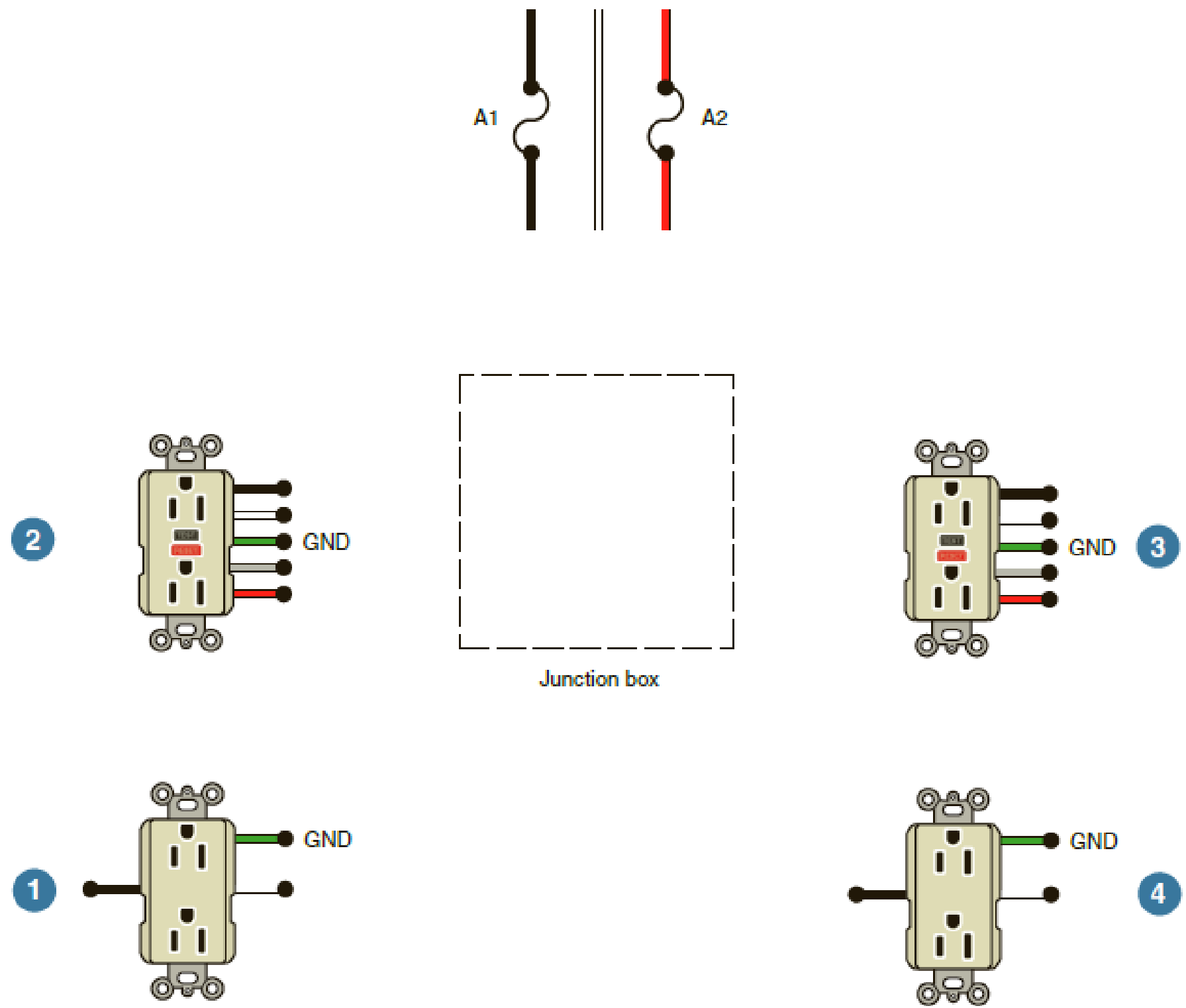
Complete the wiring diagram, connecting feed-through GFCI 2 to also protect receptacle 1, both to be supplied by Circuit A1. Connect feed-through GFCI 3 to also protect receptacle 4, both to be supplied by Circuit A2. Use colored pencils or markers to show proper color. Assume that the wiring method is EMT, where more freedom in the choice of insulation colors is possible.
Expert Solution & Answer

Trending nowThis is a popular solution!

Students have asked these similar questions
I hope the solution is on paper and not
artificial intelligence.
The subject is control system
I hope the solution is on paper and not artificial intelligence.
Vs
R1
R2
ww
ww
21x
R3
Define the Thevenin equivalent of the above circuit where R1= 10 52, R2= 30 S2, R3 = 30 12,
Vs = 70 V.
VThevenin
Number
V
RThevenin
= Number
Ω
Chapter 12 Solutions
Electrical Wiring Residential
Ch. 12 - If everything on Circuit B7 were turned on, what...Ch. 12 - From what panelboard does the kitchen lighting...Ch. 12 - How many luminaires are connected to the kitchen...Ch. 12 - What color fluorescent lamps are recommended for...Ch. 12 - a. What is the minimum number of 20-ampere...Ch. 12 - Prob. 6RCh. 12 - Prob. 7RCh. 12 - Duplex receptacles connected to the 20-ampere...Ch. 12 - Prob. 9RCh. 12 - A fundamental rule regarding the grounding of...
Ch. 12 - How many circuit conductors enter the box a. where...Ch. 12 - Prob. 12RCh. 12 - Where is the speed control for the range hood fan...Ch. 12 - Who is to furnish the range hood? _____Ch. 12 - Prob. 15RCh. 12 - Complete the wiring diagram, connecting...Ch. 12 - Each 20-ampere small-appliance branch-circuit load...Ch. 12 - a. The Code requires a minimum of two...Ch. 12 - According to 210.52, no point along the floor line...Ch. 12 - Prob. 21RCh. 12 - Electric fans produce a certain amount of noise....Ch. 12 - Prob. 23RCh. 12 - Prob. 24RCh. 12 - Prob. 25RCh. 12 - Prob. 26RCh. 12 - Prob. 27RCh. 12 - The following is a layout for the lighting circuit...
Knowledge Booster


Learn more about
Need a deep-dive on the concept behind this application? Look no further. Learn more about this topic, electrical-engineering and related others by exploring similar questions and additional content below.Similar questions
- R1 ww + R3 15+ www R2 R4 ww With the circuit diagram shown above and the values of the circuit elements listed below, find i1, 12, v1, and v2. Is = 10A, R1 = 7 ohms, R2 = 9 ohms, R3 = 7 ohms, R4 = 8 ohms (a) i1 = Number A (b) 12 = Number A (c) v1 = Number V (d) v2 = Number Varrow_forward15 ww 22 R2 ли i4 1+ V4 R1 ww R3 Solve for current i4 using superposition where R1 = 902, R2 = 36052, R3 = 360 V, and 15 = 5 A. 27052, V4 = i4 due to voltage source (V4) alone: Number A i4 due to current source (15) alone: Number A i4 = Numberarrow_forwardPV Array Va DC/DC Converter Control Circuit ис V R Fig. 2. Principle of using DC/DC converter to implement electronic load [2] 4.5 1.5 -0.5 SEPIC Converters in SOM 0 0.2 0.4 0.6 0.8 Time SEPIC Converters in SOM M 0 0.2 0.4 0.6 0.8 Time Current I-V Curve (a) 8888888 P-V Curve 0 20 40 60 80 Voltage 0 20 40 60 Voltage 80 (b) Fig. 3. Experimental results of I-V and P-V curves [2]arrow_forward
- R1 ww + R3 15+ www R2 R4 ww With the circuit diagram shown above and the values of the circuit elements listed below, find i1, 12, v1, and v2. Is = 10A, R1 = 7 ohms, R2 = 9 ohms, R3 = 7 ohms, R4 = 8 ohms (a) i1 = Number A (b) 12 = Number A (c) v1 = Number V (d) v2 = Number Varrow_forwardFind the equivalent resistance between terminals a and b in the circuit below where R₁ =6 N, R₂=12, R3=22, R4=22, and R5=150. 22 R2 R1 R5 oa R3 R4 ob Req= Number Ωarrow_forwardA Thévenin equivalent can also be determined from measurements made at the pair of terminals of interest. Assume the following measurements were made at the terminals a,b in the figure below. When a 25 k2 resistor is connected to the terminals a,b, the voltage is measured and found to be 105 V. When a 2 k resistor is connected to the terminals a,b, the voltage is measured and found to be 13 V. Find the Thévenin equivalent of the network with respect to the terminals a,b. Linear resistive network with independent and dependent sources RTh = Number ΚΩ VTh= Number V a barrow_forward
- I need help with this problem and an explanation of the solution for the image described below. (Introduction to Signals and Systems)arrow_forwardI need help with this problem and an explanation of the solution for the image described below. (Introduction to Signals and Systems)arrow_forwardI need help with this problem and an explanation of the solution for the image described below. (Introduction to Signals and Systems)arrow_forward
arrow_back_ios
SEE MORE QUESTIONS
arrow_forward_ios
Recommended textbooks for you
 EBK ELECTRICAL WIRING RESIDENTIALElectrical EngineeringISBN:9781337516549Author:SimmonsPublisher:CENGAGE LEARNING - CONSIGNMENT
 Electricity for Refrigeration, Heating, and Air C...Mechanical EngineeringISBN:9781337399128Author:Russell E. SmithPublisher:Cengage Learning
EBK ELECTRICAL WIRING RESIDENTIAL
Electrical Engineering
ISBN:9781337516549
Author:Simmons
Publisher:CENGAGE LEARNING - CONSIGNMENT
Electricity for Refrigeration, Heating, and Air C...
Mechanical Engineering
ISBN:9781337399128
Author:Russell E. Smith
Publisher:Cengage Learning
Types of House Wiring - Types of Electrical Wiring - Electrical Wiring; Author: Learning Engineering;https://www.youtube.com/watch?v=A5P-buWX-dA;License: Standard Youtube License