
Interpretation:
The evolution of phase and its compositions are to be described during the process along with the feasibility of carrying this process. The device needed to carry this process is to be determined. Also, the change in total volume of system during the process is to be estimated along with the composition at which the volume will reach its maximum value.
Concept Introduction:
In a
All the points that lies in between these curves are in two-phase region, where saturated liquid and saturated vapor coexist in equilibrium. At the edge of the
Answer to Problem 12.21P
For the given process, the phase evaluation is done along the horizontal straight line from point “a” to point “f”.
At point “a”, the system is in superheated vapor state with composition
At point “b” where first drop of saturated liquid appears and both saturated liquid and saturated vapor coexist in equilibrium. Phase composition at point “b” becomes:
At point “c”, last bubble of the saturated vapor condenses, and system is in saturated liquid state.
The composition of the system at this point “c” will be:
All the points lying on the straight-line connecting points “b” and “c” coexist in both the phases in equilibrium with total composition of the system varying from
Between points “c” and “d” the system is in superheated vapor state with composition range of
At this point “d”, the system reaches the state of saturated liquid. At this point, first bubble of saturated vapor appears which in equilibrium with the saturated liquid.
The composition of the system at this point “d” will be:
At point “e”, last drop of the saturated liquid evaporates, and system is in saturated vapor state.
The composition of the system at this point “e” will be:
In between the points “d” and “e”, both the phases saturated vapor and saturated liquid coexist in equilibrium and overall composition of the system varies as moving from “d” and “e”.
At point “f” where there is
The given process is not practically feasible.
There is no device which can be used to carry out such processes.
There is a proportional increase in the volume of the system with the increase in the total moles of the system.
The volume will reach maximum at the highest number of moles present in the system at which the composition of the system will be:
Explanation of Solution
Given information:
Below shown is the
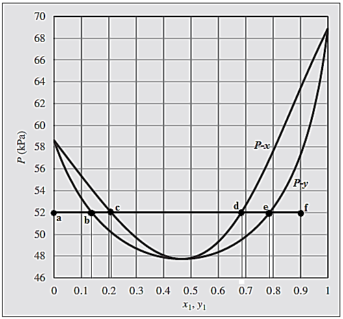
Initially, there is
Now, keeping the temperature and pressure of the system constant, pure chloroform is slowly added to the vessel until there is
On a
Point “a” lies below the
Slow addition of pure chloroform gradually shifts the system from point “a” to point “b” where is touches
Therefore, the composition at this point “b” will be:
At point “c”, last bubble of the saturated vapor condenses, and system is in saturated liquid state. Point “c” corresponds to the composition of the saturated liquid and point “b” corresponds to the composition of the last bubble (saturated vapor) which is in equilibrium with this saturated liquid.
The composition of the system at this point “c” will be:
In between the points “b” and “c”, both the phases saturated vapor and saturated liquid coexist in equilibrium and overall composition of the system varies as moving from “b” and “c”.
Addition of chloroform beyond point “c” leads the system to point “d”
In this range the system is in subcooled liquid state with overall composition of the system varying from
At this point “d”, the system reaches the state of saturated liquid as it is on the curve
The composition of the system at this point “d” will be:
At point “e”, which lies on
The composition of the system at this point “e” will be:
In between the points “d” and “e”, both the phases saturated liquid and saturated vapor coexist in equilibrium and overall composition of the system varies as moving from “d” and “e”.
Further addition of pure chloroform to the vessel takes the system to point “f” where there is
For a two-phase binary system, degree of freedom is
Therefore, the given process is not practically feasible.
Since, the given process is not practically feasible, there is no device which can be used to carry out such processes.
As temperature and pressure of the system is kept constant throughout the process, there will be proportional increase in the volume of the system as number of moles are increasing with the addition of pure ethanol in the vessel.
Since, the increase in the system volume is proportional to the moles added to the system, the maximum volume will appear at the highest number of moles present in the system, that is,
The evolution of phase and its compositions are described during the process along with the feasibility of carrying this process.
The device needed to carry this process is determined.
The change in total volume of system during the process is estimated along with the composition at which the volume will reach its maximum value.
Want to see more full solutions like this?
Chapter 12 Solutions
EBK INTRODUCTION TO CHEMICAL ENGINEERIN
- You are part of a team constructing a pipeline to transfer shale gas produced at the oceanfloor to the coastline. The temperature of the pipeline is nearly constant at 2 oC. The pipelineis made of smooth stainless steel and is 0.3 m in diameter and 100 m long. The averagevelocity of shale gas is 10 m/s and the inlet temperature is 20 oC ** Useful shale gas properties at 20 oC (Table A-12 for propane gas):(use these values for calculations and validate them later)• Density (ρ) = 18.13 kg/m3• Cp = 1974 J/kg-K• Viscosity (μ) = 8.54*10-6 kg/m-s• Pr = 0.918• k = 0.01836 W/m-Ka) Is the flow laminar or turbulent? Is the flow hydrodynamically and thermally fully developed?(circle your answer below and provide justification. • Laminar vs. Turbulent• Hydrodynamically developing vs. developed• Thermally developing vs. fully developedJustification: b) Calculate convective heat transfer coefficient (h). c) Calculate the exit temperature of the shale gas. d) Are the shale gas properties…arrow_forward3) A pilot-plant Podbielniak centrifugal extractor operating at 11,400 x g (this is G₁) is capable of processing 500 mL/min of filtered fermentation broth and 125 mL/min organic solvent, giving a recovery of 95%. The rotating cylinder inside the extractor has a diameter of 20 cm and is 2.5 cm wide. You need to scale up this extraction by using a larger Podbielniak extractor that has a diameter of 91 cm and width of 91 cm and delivers 2,300 x g (G2). What flow rates (in L/min) should be used in the larger extractor to achieve the same recovery efficiency?arrow_forward7) You are tasked with separating two proteins by ion exchange chromatography on a 30 cm long column with an inner diameter of 2 cm. The resin has a diameter of 100 μm and a void fraction of 0.3, and your mobile phase flows through the column at a rate of Q = 5 cm³/min. The Van Deemter coefficients A, B, and C have been determined to be 0.0228 cm, 0.0036 cm²/min, and 0.00053 min, respectively, for both proteins. Protein A elutes from the column with an average retention time of 27 min and standard deviation of 0.8 min. Protein B elutes from the column. with an average retention time of 33.8 min and standard deviation of 1.0. a) How many theoretical plates does the column contain? b) What flow rate (Q) will give you the maximum resolution? c) What is the minimum height of a theoretical plate for the system?arrow_forward
- 1 5) You are asked to design a moving bed adsorption process using two columns (see the figure below). Your feed contains 100 mg/L protein and flows through both columns at 4 m³/h. Fresh resin enters the bottom of both columns (resin does not flow from the bottom column to the top column). The maximum resin flow rate that your pumps can comfortably handle is 120 kg resin/h. Experimental data suggest that the adsorption equilibrium can be modeled as qi=4ci where qi is in g protein/kg resin and c; is in g protein/L broth. (Pay attention with units!) a) What is the lowest concentration of proteins that you could get in the effluent from column 1 (indicated by the *) in mg/L? (Hint: set up a mass balance) 0.25 , * 1 2 b) What should be the flow rate of resin (in kg/h) into the second column (B2) if your overall process needs to remove 99% of the protein?arrow_forward6) Instead of moving bed adsorption, you decide to try fixed bed adsorption with a different resin for removal of your protein. Your column is 25 cm long with an inner diameter of 5 cm. The resin packed in the column has a density of 1.5 g/cm³ and a void fraction of 0.25. Equilibrium data suggests that the protein binding to the column follows a Langmuir isotherm with an Stot = 6.25 g protein/kg resin and Keq = 2.58 L broth/g protein. The feed contains 100 mg/L protein and flows through the column at 500 mL/h. The calculated binding capacity of the column under these conditions is 945 mg protein. a) After 17.7 h, you detect an unacceptable level of protein in the column effluent. What is the length of unused bed? b) After deciding that this process will work well for separation, you need to scale up to a 1 m long column with the same diameter. If all else but length of the column is held constant, how long will you be able to run the column before breakthrough?arrow_forward2) A bioprocess stream contains two components: 60 g/L A (the desired bioproduct) and 40 g/L B (a contaminant). The partition coefficients in an extraction process are KA = 14.0 and KB = 0.5. If the stream is fed into a 5-stage countercurrent extractor at 25 L/min and solvent enters at 5 L/min, calculate the amount of each component in the extract phase at the outlet of the extractor.arrow_forward
- What flow rate (Q, in L/min) will give the maximum resolution if you scale up the process in problem 7 to a column with a diameter of 50 cm? (Use the conditions in the problem statement, not the optimal flow conditions calculated in the problem).arrow_forwardYou are asked to separate two proteins via size exclusion chromatography. Your column is 5 cm in diameter and 25 cm in length. You add 50 g (dry weight) of Sephacryl gel (density = 1.25 g/cm³) to the column. The volume outside of the gel and pores is 77 cm³. The column operates at a flow rate of 1 mL/min to not compress the resin. The average retention times of proteins A and B are 244.5 and 273 min, respectively. Under the given conditions, you calculate that there are 1600 theoretical plates in the column. (This problem continues onto the next page). a) What is the volume inside of the pores? b) What are the elution limits of this system (i.e., what re the minimum and maximum volumes that particles will elute in)? c) What are the gel partition coefficients of proteins A and B for this system? d) What are the peak widths for both proteins? e) Assuming the peak widths are 22 mL and 28 mL for proteins A and B, respectively (these values are not necessarily correct), what is the…arrow_forward1) Indicate whether each statement below is True or False: a) In extractions, small proteins usually end up in the heavy phase. b) In extractions, large proteins usually end up in the heavy phase. c) Tie line length on a phase diagram has no effect on protein partitioning. d) For extraction, we assume that each stage reaches equilibrium. e) Isotherms that are concave down lead to self-sharpening solute fronts in adsorption. f) When scaling up an adsorption unit, the LUB scales proportionally with adsorber length. g) For chromatography, separation efficiency increases when HETP increases. h) In size exclusion chromatography, smaller molecules elute from the column first. i) In hydrophobic interaction chromatography, very hydrophobic proteins elute in water. j) Molecules at very high concentrations elute from the column as a perfect Gaussian peak. k) In chromatography scale-up, resolution will increase as column diameter increases. 1) A good adsorbent typically has no porosity. m)…arrow_forward
- Chemical Engineering Use the psychrometric chart and demonstrate the linear interpolation method to obtain -0.52 KJ/KgDA. This is the enthalpy deviation. The exercise is uploaded below.arrow_forwardChemical Engineering Use the psychrometric chart. The remaining curves on the psychrometric chart are almost vertical and convex to the left, with labeled values (on Figure 8.4-1) of 0.05, 0.1, 0.2, and so on. (The units of these numbers arekJ/kg DA). Thesecurves are usedto determine theenthalpyof humid air that is not saturated. The procedure is as follows: (a) locate the point on the chart corresponding to air at its specified condition; (b) interpolate to estimate the enthalpy deviation at this point; (c) follow the constant wet-bulb temperature line to the enthalpy scale above the saturation curve, read the value on that scale, and add the enthalpy deviation to it. Also, you will see the exercise on the piece of paper.arrow_forwardCalculate the permeability of the bed of ion-exchange particles in Example 11.1.arrow_forward
 Introduction to Chemical Engineering Thermodynami...Chemical EngineeringISBN:9781259696527Author:J.M. Smith Termodinamica en ingenieria quimica, Hendrick C Van Ness, Michael Abbott, Mark SwihartPublisher:McGraw-Hill Education
 Elementary Principles of Chemical Processes, Bind...Chemical EngineeringISBN:9781118431221Author:Richard M. Felder, Ronald W. Rousseau, Lisa G. BullardPublisher:WILEY
 Elements of Chemical Reaction Engineering (5th Ed...Chemical EngineeringISBN:9780133887518Author:H. Scott FoglerPublisher:Prentice Hall
 Industrial Plastics: Theory and ApplicationsChemical EngineeringISBN:9781285061238Author:Lokensgard, ErikPublisher:Delmar Cengage Learning
 Unit Operations of Chemical EngineeringChemical EngineeringISBN:9780072848236Author:Warren McCabe, Julian C. Smith, Peter HarriottPublisher:McGraw-Hill Companies, The


